1. Introduction
Bonding wires transmit signals from various semiconductor devices such as integrated circuits, radio frequency (RF), field-programmable gate array (FPGA), light-emitting diode (LED), and memory package. It is important to select bonding wires of materials with excellent corrosion resistance and bonding degradation properties since the efficiency and reliability of semiconductor modules can be directly affected. Materials for bonding wires include gold (Au), silver (Ag), aluminum (Al), copper (Cu), palladium-coated copper (Pd-coated Cu), palladium-doped copper (Pd-doped Cu), and gold-coated copper (Au-coated Cu), while Au wires with the best corrosion resistance have been used most commonly. In addition to corrosion resistance, Au wires have a low hardness of approximately 216 MPa (Hv), which provides the benefits of superior processability and bonding properties by rapidly forming an intermetallic compound (IMC) with an Al pad. Although bonding wires of alternative materials are being developed due to high prices, Cu-Pd wires appear to have the highest usage as Au accounts for 16% and Cu-Pd accounts for 45% among the wire materials with high usages as of 2017. In Cu-Pd wires, the high corrosiveness of Cu wires is mitigated by a palladium coating, but the inherently high oxidation property of Cu cannot be completely prevented by the Pd coating. Furthermore, Cu is high in hardness at approximately 369 MPa (Hv) and has the disadvantages of poor processability and bonding properties compared to Au and Ag wires since the formation rate of the intermetallic compound with an Al pad is low. On the other hand, Ag wires are similar in hardness to Au wires at 250 MPa (Hv) and have excellent electrical conductivity, thermal conductivity, and corrosion resistance, serving as a new alternative to Au
1-6).
The wire bonding methods largely include ball bonding and wedge bonding. In ball bonding, an arc is generated at the tip of a wire to form a free air ball (FAB), which is then bonded using ultrasonic waves. Wedge bonding is primarily a method of bonding Al wires by applying ultrasonic waves with a tool called a wedge. Au wires are typically used in ball bonding while Al, Cu, and Au wires are used in wedge bonding
6).
In this study, three types of wires were used in total, including two types of Ag wires and one type of Au wires. Modules were prepared by applying wire ball bonding to dummy modules consisting of a silicon chip bonded to a bismaleimide triazine (BT) printed circuit board (PCB). The ultrasonic bonding characteristics of each bonding wire material were compared by conducting a highly accelerated stress test (HAST) on the prepared modules and analyzing the bonding strength and microstructure before and after the test.
2. Experimental Method
2.1 Wire Bonding
BT PCBs with an Au-plated Ni pad were used as substrates in the experiment, and Si chips with an Al pad on the top were used as dummy chips. 97.3% Ag wires, Au-coated 97.3% Ag (ACA) wires, and 99.99% Au wires were chosen as bonding wires, and their bonding characteristics were compared.
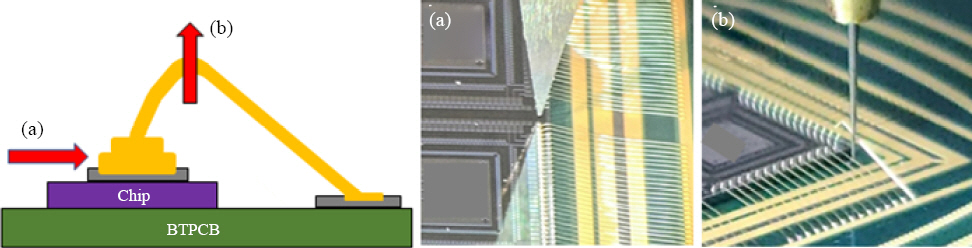
Fig. 1 shows the process schematic. The diameter of all wires was 20.3 ŃÄø (0.8 mil), and the bonding conditions were as shown in
Table 1. After wire bonding, the surface and cross-sectional microstructures were analyzed through scanning electron microscope (SEM) analysis, and the initial bonding characteristics were compared by measuring the bonding strength.
Fig.┬Ā1
Schematic explanation of wire ball bonding process

Table┬Ā1
|
Wre Type |
Ag wire |
ACA wire (Au Coated Ag) |
Au wire |
|
Composition |
97.3% Ag |
97.3% Ag |
99.99% Au |
|
Coating |
- |
Au 90 nm |
- |
|
Thickness |
20.32 ŃÄø (0.8 mils) |
|
Process
|
1 st
|
2 nd
|
EFO
|
1 st
|
2 nd
|
EFO
|
1 st
|
2 nd
|
EFO
|
|
Gas (L/min) |
0.25 |
off |
off |
|
Current (mA) |
50 |
100 |
18 |
70 |
100 |
40 |
62 |
100 |
25 |
|
Time (us) |
5 |
15 |
505 |
15 |
15 |
235 |
10 |
15 |
380 |
|
Force (gf) |
15 |
50 |
|
25 |
50 |
- |
18 |
50 |
- |
2.2 HAST Test
The HAST test was conducted on the wire bonding modules to examine the characteristics of corrosion and degradation caused by high temperature and moisture permeation. To eliminate residual moisture inside the modules prior to the test, the modules were baked in an oven at 175Ōäā for 6 h and in an HAST chamber (PC-R8D(HIRAYAMA)) at 130Ōäā/85% RH for 168 h. After the test, the bonding strength of the bonding wires was measured and compared to the initial characteristics, and SEM analysis was conducted to analyze micro defects after pre-treating the cross-section of the bonding interface using a focused ion beam (FIB) device.
2.3 Bonding Strength Test
A bonding test machine (Dage 4000, Nordson Co. Ltd., USA) device was used for the bonding strength test, and the wire ball shear test (BST) and the wire ball pull test were conducted.
Fig. 2 shows the test directions and photographs. The ball shear test was performed at a test rate of 500 ŃÄø/s and a test height of 2.5ŃÄø, and the wire pull test was performed at a test rate of 1,000 ŃÄø/s. The bonding wires were examined before and after the HAST test to compare the bonding strength characteristics depending on the wire alloy.
Fig.┬Ā2
Schematic and optical micrograps of bonding strength measurement, (a) wire ball shear test and (b) wire ball pull test
3. Experimental Results
3.1 Initial Bonding Characteristics of Bonding Wires
After wire bonding, the appearance and cross-sectional SEM analysis confirmed adequate bonding (
Fig. 3,
4), and the initial BST measurement produced similar results between the Au wire at 23.37 gf, Ag wire at 24.40 gf, and ACA wire at 23.43 gf (
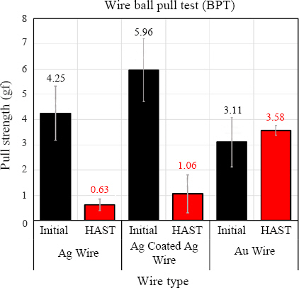
Fig. 5). The BPT test results indicated that the ACA wire had the highest tensile strength with the Au wire at 3.11 gf, Ag wire at 4.25 gf, and ACA wire at 5.96 gf (
Fig. 6).
Fig.┬Ā3
Optical and SEM micrographs of wire bonding modules, (a) Ag wire, (b) Au coated Ag wire (ACA) and (c) Au wire
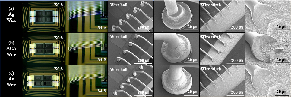
Fig.┬Ā4
Cross-sectional SEM micrographs of ultrasonic bonding interfaces of wire bonding modules, (a) Ag wire, (b) Au coated Ag wire (ACA) and (c) Au wire
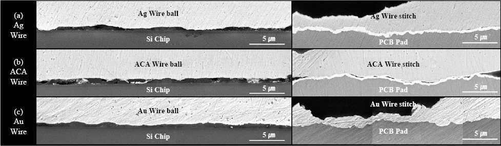
Fig.┬Ā5
Bonding strength comparison with before and after reliability test: wire ball shear test

Fig.┬Ā6
Bonding strength comparison with before and after reliability test: wire ball pull test
3.2 Bonding Characteristics After HAST Test
Fig. 5 and
Fig. 6 show the bonding strength measurements of the Ag wire following the HAST test. The bonding strength measured after the test was 6.12 gf, about 75% lower than the initial value. On the other hand, the bonding strength of the ACA wire was about 47% lower at 12.54 gf, confirming that its bonding strength was better than that of the Ag wire.
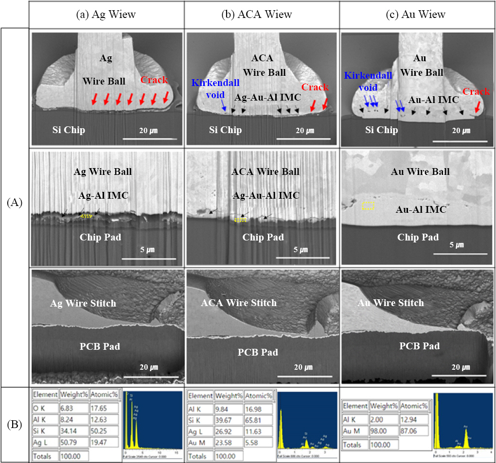
As shown in
Fig. 7, the cross-sectional microstructure analysis of the bonding wire interfaces indicated a thick Au-Al intermetallic compound (IMC) layer with a high Au content, as well as micro cracks at the end of the bonding interface. On the bonding interface of the ACA wire, a thin Ag-Au-Al intermetallic compound layer was observed, and a crack was found to propagate from the end of the bonding interface to around the intermetallic compound layer (
Fig. 7). Since spherical free air balls are bonded under pressure in the wire ball method, the bonding interface is most vulnerable at its two ends. This explains why the cracks occurred at both ends of the bonding interface, while the intermetallic compound layer formed within the bonding interface appeared to prevent the cracks from propagating further. On the other hand, a very long crack occurred in the bonding interface of the Ag wire, accounting for 69% of the bonding interface, and progressed along the finely formed intermetallic compound layer.
Fig.┬Ā7
FIB cross-sectional (A) SEM micrographs and (B) EDS analysis results after reliability test, (a) Ag wire, (b) Au coated Ag wire (ACA) and (c) Au wire
A previous study by Jaafar and Tseng showed that, among Au, Ag, and Cu wires, Au wires had the highest reactivity with an Al pad, resulting in the fastest formation of an intermetallic coumpound
5). It was also reported that ACA wires formed an AuAl
2 intermetallic compound at the top and an Ag-Al-Au intermetallic compound at the bottom after the wires were stored at a high temperature of 175Ōäā for 500 hours
7). Despite a low Au content, ACA wires reacted with the Al pad first, forming an Au-Al intermetallic compound. Although an Au-Al intermetallic compound is generally known to cause cracks in the bonding interface of Au wires, according to the study, the strength of AuAl
2 in the Au-Al intermetallic compound is brittle and vulnerable at the bonding interface, while intermetallic compounds such as Au
2Al and Au
4Al with a higher Au content (or a relatively lower Al content) are ductile and more resistant to crack propagation
8). In this study, an Au-Al intermetallic compound layer with a high Au content was also observed, which is believed to have prevented the crack from propagating.
Kirkendall voids, which are also problematic along with the intermetallic compound at the bonding interface of Au wires, reduce the bonding reliability due to the initiation and propagation of cracks. Au alloy wires can be used to prevent Kirkendall voids, and some studies have reported that Kirkendall voids do not occur in Au-15 % Ag-5 % Pd alloy wires even after storing them at a high temperature of 180Ōäā for 1500 hours
9). Kirkendall voids are created as a result of the difference in the interdiffusion rate of Au and Al and the difference in the volume of the formed IMC during the formation process of the Au-Al intermetallic compound. In the Au-Ag-Pd alloy wire, an Au-Ag-Al layer is formed below an Au-al layer, reducing the interdiffusion reaction of Au-Al. In this study, about five Kirkendall voids were found at the bonding interface of the Au wire, while about one Kirkendall void was observed at the bonding interface of the ACA wire with an Au- Ag-Al layer, indicating that the Ag content was effective in preventing Kirkendall voids.
4. Conclusions
In this study, 20.32 ŃÄø (0.8 mil) wires in 97.3 % Ag, Au-coated 97.3 % Ag(ACA), and 99.99 % Au materials were used to prepare dummy packages through ball bonding and stitch bonding. BST and BPT were measured before and after the HAST test conducted at 130Ōäā and 85%RH, and the changes in the microstructure characteristics of the ultrasonic bonding interface of the wires were compared.
1) The BST results showed that the initial bonding strength was similar at about 23-24 gf, but the bonding strength of the Ag, ACA, and Au wires decreased by about 75%, 47%, and 17%, respectively, after the HAST test.
2) In the microstructure analysis, cracks were found to occur and propagate from the ends of the bonding interface, while the Au-Al intermetallic compound at the bonding interface of the ACA and Au wires with a high Au content was thought to have prevented the cracks from propagating.
3) Kirkendall voids were observed at the bonding interface of the Au wire, while almost none was found at the bonding interface of the ACA wire. It is believed that the Ag-Au-Al intermetallic compound formed at the bonding interface of the ACA wire acted as an obstacle to the Au-Al interdiffusion reaction, reducing the formation of Kirkendall voids.
Acknowledgements
This work was supported by the Technology Innovation Program Materials and Components Development Program (Grant No. 20011427) funded by the Korean Ministry of Trade, Industry, and Energy (MOTIE) in the Republic Korea.
References
1. J. P. Jung, Ultrasonic Bonding of Electronic Parts, Proceedings of the 2008 Autumn Meeting of KWJS, Incheon. (2008) 7ŌĆō9.
4. P. Lall, S. Deshpande, and L. Nguyen, Reliability of Copper, Gold, Silver, and PCC Wirebonds Subjected to Harsh Environment,
Proceedings of Electronic Components and Technology Conference (ECTC). IEEE 68th(2018) 724ŌĆō734.
https://doi.org/10.1109/ECTC.2018.00113
[CROSSREF] 5. N. B. Jaafar and E. W. L. Ching, Comparison of Au/Al, Cu/Al and Ag/Al in Wirebonding Assembly and IMC Growth Behavior,
Proceedings of Electronics Packaging Technology Conference (EPTC). IEEE 18th(2016) 10ŌĆō12.
https://doi.org/10.1109/EPTC.2016.7861432
[CROSSREF] 6. J. M. Kim, J. P. Jung, S. H. Kim, and J. H. Pack, Packaging Technology in Electronics and 3-dimensional Stacking Packaging, J. Korean Weld. Join Soc. 23(2) (2005) 23ŌĆō31.
7. Y. W. Tseng, F. Y. Hung, and T. S. Lui, Wire bonding of Au-coated Ag wire, bondwire properties, bondability and IMCs formation, Proceedings of European Microelectronics Packaging Conference. (2015) 1ŌĆō4.
9. H. Liu, Q. Chen, Z. Zhao, Q. Wang, J. Zeng, J. H. Chae, and J. S. Lee, Reliability of Au-Ag Alloy Wire Bonding,
Proceedings of Electronic Components and Technology Conference(ECTC). IEEE 60th(2010) 234ŌĆō239.
https://doi.org/10.1109/ECTC.2010.5490906
[CROSSREF]


 PDF Links
 PubReader
 ePub Link
 Full text via DOI
 Download Citation
 Print
Print


