Warning: fopen(/home/virtual/kwjs/journal/upload/ip_log/ip_log_2024-04.txt): failed to open stream: Permission denied in /home/virtual/lib/view_data.php on line 88 Warning: fwrite() expects parameter 1 to be resource, boolean given in /home/virtual/lib/view_data.php on line 89 A Study on Deformation According to Steel Constraints During Thick-Plate Fillet Welding and Line Heating

J Weld Join > Volume 41(6); 2023 > Article
Park, Park, Park, Yang, Park, Roh, Yi, Kim, and Lee: A Study on Deformation According to Steel Constraints During Thick-Plate Fillet Welding and Line Heating

Abstract

Most of the products manufactured in shipyards are steel structures, and they are mainly manufactured using welding techniques. There are various welding methods, and use of very high heat is common. Thermal deformation occurs due to the high heat of welding when manufacturing steel structures, and leads to errors compared to the design. Methods to ensure dimensional accuracy include optimizing the welding order, applying reverse setting before welding by predicting thermal deformation in advance, and suppressing thermal deformation through constraints. However, the most popular method for this purpose is flame straightening. This study proposes a method of utilizing steel constraints during welding and line heating to control thermal deformation by welding. Analytical verification confirmed the differences according to the presence or absence of steel constraint application and the time of application. Consequently, it was confirmed that line heating is effective in correcting thermal deformation and steel constraints can maximize the effect of line heating.

1. Introduction

Most of the products that shipyards manufacture are steel structures. There are many ways to manufacture steel structures, but in the shipbuilding industry, they are mainly made by welding steel materials together. There are many different ways to weld, but they all involve the use of very high heat to fuse steel materials or steel and filler metal materials. While welding generally provides better watertightness, airtightness, and strength than other manufacturing methods, the high heat generated during welding can cause thermal deformation of the steel structure, resulting in errors compared to the initial design. Fig. 1 shows the deformation data measured by 3D scanning after fillet welding, indicating that deformation has occurred after welding.
Fig. 1
Welding and 3D scanning data after welding
jwj-41-6-508-g001.jpg
There are several methods for securing dimensional accuracy, such as optimizing the welding sequence1,2), predicting thermal deformation in advance and applying reverse deformation before welding (reverse setting)3), and suppressing thermal deformation through constraints, but the most widely used method in the field is flame straightening.
Flame straightening aims to relieve residual stresses and correct deformations in welded structures by heating with gas and is mainly used for the latter purpose in the field. Deformation correction is performed to process misalignment or interference of the structure to the dimensions required by the drawing or to induce reverse deformation to correct deformation caused by welding, and there are methods such as line heating (continuous or intermittent), crisscross heating, lattice heating, and point heating. In particular, the most widely used method in the field is line heating.
Fig. 2 shows the three-dimensional scanning data after line heating, which shows that the overall deformation has been canceled out.
Fig. 2
Line heating and 3D scanning data after line heating
jwj-41-6-508-g002.jpg
These weld corrections can have varying results depending on the operator’s skill and require additional labor and expense, so it is important to induce the weld deformation as little as possible. In particular, as the number of allowable flames straightening attempts may be limited by the customer or steel grade, if welding correction work cannot be avoided, it should be minimized by minimizing the initial thermal deformation.
This study aims to present a method to minimize thermal deformation with steel constraints during welding and line heating and to investigate the thermal deformation behavior according to steel constraints.

2. Evaluation overview

2.1 Evaluation target

This study was conducted to examine the fabrication variants of the topside module bearing node applied to offshore projects, as shown in Fig. 3. The bearing node is a structure located between the topside module supporter (TMS) and the topside module to support the self-weight and environmental loads transmitted through the offshore topside module and to fix the position of the topside module, which requires the use of thicker steel plates than those applied to general merchant ships.
Fig. 3
Bearing node and TMS
jwj-41-6-508-g003.jpg
For these offshore structures, welding is not just about connecting steel to steel but also about improving weld strength and fatigue performance through complete joint penetration (CJP) and partial joint penetration (PJP), as shown in the second and third images in Fig. 4.
Fig. 4
Normal fillet, CJP, PJP
jwj-41-6-508-g004.jpg
However, welding methods like CJP and PJP induce large thermal deformation due to excessive heat input by welding, which can cause difficulties in installing each part in the correct position and may require correction work during the product manufacturing process. Fig. 5 shows the configuration and placement of the bearing nodes.
Fig. 5
Configuration of bearing node
jwj-41-6-508-g005.jpg
For example, in the first process of bearing node manufacturing, Top plate - Web - Btm. plate welding, the gap between the two facing plates becomes narrower due to the angular deformation that occurs after welding, which makes it difficult to insert the next part, the quarter pipe, causing difficulties in manufacturing.
In order to solve these problems, the aforementioned methods of weld sequence optimization, reverse setting, steel constraints, and flame straightening can be applied in the manufacturing process.
Among these methods, this study aims to propose a method that enables the fabrication of bearing nodes using steel constraints and flame straightening to control thermal deformation. Fig. 6 shows the thermal deformation constraint tool applied in this study, which can be installed and removed at any time before or after the completion of product manufacturing through mechanical fastening, unlike the conventional method of welding the steel piece to the steel support. This prevents the spring-back phenomenon that occurs when the tool is cut for turnover or movement while using a conventional welded constraint tool, thereby maintaining the effect of constraining thermal deformation until the completion of product manufacturing.
Fig. 6
Deformation constraint tool
jwj-41-6-508-g006.jpg

2.2 Thermal deformation evaluation methods

The thermal deformation evaluation was performed by the strain as direct boundary (SDB) method with two- dimensional shell elements and the thermo-elastic- plastic (TEP) method with three-dimensional solid elements using MSC Marc, a general-purpose nonlinear finite element code.
The SDB method realizes actual welding deformation by using virtual temperature and virtual coefficient of thermal expansion in finite element analysis based on experimental measurement data of welding angular deformation amount according to plate thickness and length of welding leg4-9).
The TEP method performs elastoplastic analysis from the heat conduction equation and the thermal deformation due to temperature difference, which is a realistic analysis method that can consider welding speed, sequence, direction, arc shape, heat transfer through conduction, heat loss through convection, etc.

2.2.1 The SDB method

There are a total of 228 welding seams in the bearing node, excluding the stopper, and if we break it down by production stage and consider the welding order and direction, the following number of cases are derived for the welding sequence in each production stage.
  • ① [Web] to [Top plate]: 6 beads → 6!×26 = 46,080 cases

  • ② [Web] to [Btm. plate]: 6 beads → 6!×26 = 46,080 cases

  • ③ [Quarter pipe] to [Top plate / Btm. plate / Web]: 16 beads → 16!×216 = 1.37E+18 cases

  • ④ Mid. plate] to [Web / Quarter pipe]: 24 beads → 24!×224 = 1.04E+31 cases

  • ⑤ [Stiff.] to [Btm. plate / Web / Mid. plate]: 96 beads → 96!×296 = 7.86E+178 cases

  • ⑥ [Brk.] to [Web / Mid. plate]: 80 beads → 80!×280 = 8.65E+142 cases

This would require [46,080×46,080×1.37E+18×1.04E+ 31×7.86E+178×8.65E+142=2.05E+380] analyses to find a single optimal welding sequence for the final structure, which is not feasible.
Therefore, the deformation of the bearing nodes was calculated using the SDB method, commonly recognized as a simplified analysis method, to evaluate the manufacturability and post-production flatness of the product.
Using the strain calculation method, five analyses were performed on the bearing node, as shown in Fig. 7, and the purpose of each analysis was described.
  • ① Top - Web - Btm. without Const.: Checking whether a quarter pipe can be inserted

  • ② Top - Web - Btm. with Const.: Checking whether quarter pipe can be inserted according to the Top / Btm. plate constraints

  • ③ Full node: Checking the Top / Btm. plate flatness according to node production

  • ④ Stopper: Checking the flatness of the TMS contact surface after fabricating the stopper

  • ⑤ Stopper to Node: Checking the flatness of each part upon completing the node-bearing set

Fig. 7
Analysis for checking the deformation of the bearing node
jwj-41-6-508-g007.jpg
Of these, only analyses ① and ② are relevant to this study. The welding section information applied to the bearing node is shown in Fig. 8, and the thickness of the web and main plate applied to the SDB method is 30t and 50t, respectively.
Fig. 8
Information of bead section
jwj-41-6-508-g008.jpg
Analysis ① was conducted to check whether the quarter pipe, the next installation member, can be inserted when welding the top and bottom plates and the web, and as a result, the quarter pipe could not be inserted due to the large out-of-plane angular deformation of the upper and lower plates.
Analysis ② was performed to verify that the quarter pipe could be inserted by constraining the out-of-plane angular deformation of the top and bottom plates identified in Analysis ①. The results of analyses ① and ② will be discussed later.

2.2.2 The TEP method

In order to better evaluate the amount of angular deformation generated during thick plate fillet welding and to realize the effect of deformation control through flame straightening, the TEP method was used.
However, since evaluating all welding scenarios would result in a significant number of analysis scenarios, as mentioned earlier, a simple thick plate fillet model was used to analyze the deformation due to welding and flame straightening. Fig. 9 is the FE model for the TEP method. The welding was performed on the left bead first, and the progression direction of both beads was the same from front to back in the figure. The steel constraints were treated as boundary conditions for analysis efficiency. In addition, due to the nature of the analysis technique, bead elements are generated during the welding process, so an idealized general fillet model was applied to improve convergence by preventing over-deformation of the elements due to welding heat input, and the results were compared as a case study.
Fig. 9
TEP FE model
jwj-41-6-508-g009.jpg
Welding heat conditions followed the welding procedure specification (WPS) provided in the field, and the heating condition for flame straightening was selected based on the experiments conducted in the field as shown in Fig. 10, where the temperature below AC1 was uniformly applied to the entire straightening section to prevent phase transformation of the material.
Fig. 10
Test result of line heating
jwj-41-6-508-g010.jpg
For heat dissipation, the convection coefficient of natural convection (10 W/m2K) was used. Table 1 shows the convection coefficients for different convection states.
Table 1
Approximate values of heat transfer coefficient10)
Conditions of heat transfer W/(m2K)
Gases in free convection 5-37
Water in free convection 100-1,200
Oil under free convection 50-350
Gas flow in tubes and between tubes 10-350
Water flowing in tubes 500-1,200
Oil flowing in tubes 300-1,700
Molten metals flowing in tubes 2,000-45,000
Water nucleate boiling 2,000-45,000
Water film boiling 100-200
Film-type condensation of water vapor 4,000-17,000
Dropsize condensation of water vapor 30,000-140,000
Condensation of organic liquids 500-2,300
Although this is a simple fillet model with only two beads, considering whether and when to constrain the main plate leads to the scenario shown in Table 2.
Table 2
Constraint scenarios for each step
Step Constraint scenarios
1 2 3 4 5 6 7 8 9 10 11 12 13 14 15 16
Welding (1st / 2nd) X O X X X O O O X X X O O O X O
Cooling w/ Const. X X O X X O X X O O X O O X O O
Cooling w/o Const. - - O - - O - - O O - - O - O -
Line heating X X X O X X O X O X O O X O O O
Cooling w/ Const. X X X X O X X O X O O X O O O O
Cooling w/o Const. - - - - O - - O - O O - O O O O
Of the 16 scenarios, scenarios 1, 2, 6, 12, and 16 that were actually applicable in the field were used for the analysis. The remaining scenarios were excluded from the evaluation due to the impracticality of applying steel constraints after deformation had already occurred and the difficulty of applying the constraints.
The scenarios selected for the analysis are summarized as follows:
  • ① SC1: Steel constraints are not applied.

  • ② SC2: Steel constraints are applied only during welding.

  • ③ SC6: Steel constraints are removed upon completing cooling after welding (before flame straightening).

  • ④ SC12: Steel constraints are retained until flame strai- ghtening is completed.

  • ⑤ SC16: Steel constraints are removed upon completing cooling after flame straightening.

Scenarios 6 and 16 have the condition of removing steel constraints at the end of cooling after welding and at the end of cooling after flame straightening, respectively, and undergo an additional cooling process without steel constraints as deformation due to the spring-back phenomenon occurs with the removal of steel constraints. (Cooling w/o Const.)

3. Results and Discussion

3.1 Analysis of deformation characteristics through the SDB method

As a result of analysis ①, shown in Fig. 11, the out-of- plane angular deformation of the top and bottom plates was large, as mentioned earlier. The gap between the top and bottom plates was reduced by 17.7 mm from the original, exceeding the allowable installation tolerance of 6 mm for the quarter pipe insertion, which required welding correction work.
Fig. 11
Analysis result of SDB without constraint (Scale factor = 10)
jwj-41-6-508-g011.jpg
As a result of analysis ②, shown in Fig. 12, steel constraints were applied to the area where the quarter pipe was inserted, and as a result, the gap between the top and bottom plates was reduced by 5.2 mm compared to the original, allowing the quarter pipe to be inserted.
Fig. 12
Analysis result of SDB with constraint (Scale factor = 10)
jwj-41-6-508-g012.jpg
In analysis ①, the maximum gap contraction occurred at the free edge of the plate, but in analysis ②, the effect of the constraint shifted the location to the inside of the plate. This means that when the steel constraint that constrains the deformation of the upper and lower plates is removed, the deformation due to the spring- back phenomenon can recur. However, it solves the most difficult part of manufacturing a bearing node, as it allows the quarter pipe to be inserted, and the inserted quarter pipe acts as a constraint. The spring-back phenomenon will be discussed in the results of the analysis using the TEP method.

3.2 Analysis of deformation characteristics through the TEP method

The effect of flame straightening and steel constraints was confirmed by comparing the deformation behavior of different scenarios through the analysis using the TEP method.
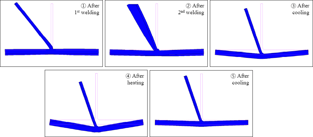
The step-by-step behavior of scenario 1 with typical welding and flame straightening conditions is shown in Fig. 13.
Among the overall behaviors, the behavior related to out-of-plane angular deformation is examined step by step as follows:
  • ① During 1st bead welding, shrinkage of the bead causes angular deformation of the web in the direction of the 1st bead.

  • ② During 2nd bead welding, shrinkage of the bead causes angular deformation of the web in the direction of the 2nd bead, with some recovery.

  • ③ While cooling after welding, shrinkage of the base metal received by the 1st and 2nd weldings causes angular deformation of the main plate in the direction of the welding seam.

  • ④ Angular deformation of the main plate deepens due to expansion of the base metal due to heat input from the back side of the weld during flame straightening.

  • ⑤ Angular deformation is recovered due to shrinkage of the back side of the weld that received heat input during cooling after flame straightening.

Fig. 13
Staged deformation behavior during fillet welding and line heating of SC 1 (Scale factor = 30)
jwj-41-6-508-g013.jpg
The step-by-step behavior outlined above is typical of the behavior that predominates at each stage of the analytical model used in this study.
In an actual phenomenon, beads are cooled down at the same time when heat input is received, resulting in shrinkage behavior, and the base material is conducted with heat, resulting in expansion behavior as opposed to beads. Additionally, the behavior may vary depending on the length of the welding seam. For example, if the welding seam is quite short, the base metal may be heated and expand later due to heat conduction caused by the time difference during cooling after welding. Conversely, if the welding seam is very long, even during welding, the weld start position may have been cooled significantly, resulting in a deformation close to the final state, and at the same time, the recovery of stiffness as temperature drops may affect the deformation of the still high temperature region.
The step-by-step behavior of scenario 16 with steel constraints applied at all step is shown in Fig. 14 below.
Scenario 16 shows a much different behavior than scenario 1 due to the effect of constraints. While the heat input part of the welding to shrink as it cools down, the out-of-plane angular deformation at the free end is suppressed by the steel constraints, resulting in an arch-like bend in the main plate on the left and right sides of the web, unlike in scenario 1.
Fig. 14
Staged deformation behavior during fillet welding and line heating of SC 16 (Scale factor = 30)
jwj-41-6-508-g014.jpg
Comparing the results of cooling after welding and cooling after flame straightening in scenarios 1 and 16, flame straightening affects the out-of-plane angular deformation offset of the main plate. In particular, in scenario 16, the effect of constraints has caused the final state with the constraints removed to deform in the opposite direction to the angular deformation seen upon completion of cooling after welding.
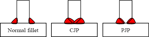
As mentioned earlier, this is a result of applying an idealized TEP model for the purposes of the case study. If CJP or PJP had been applied, the amount of out-of -plane angular deformation caused by the weld would have been greater due to the higher heat input, and the result of the correction work may not have been in the reverse direction of the out-of-plane angular deformation caused by welding. These, however, can vary considerably depending on the conditions of welding and flame straightening, and it is significant that this study has focused on verifying the effects of flame straightening and constraints and verified them.
Table 3 shows the out-of-plane angular deformation results of the main plate for each scenario at the end of cooling after welding and at the end of cooling after flame straightening. Since the deformation of the main plate does not maintain perfect straightness, it is divided into the radian value in the section where the straightness is maintained and the maximum deviation in the out-of-plane direction of the lower surface of the main plate after deformation. Scenarios 12 and 16 were excluded from the analysis as the steel constraints were not removed until just before the end of cooling after welding.
Table 3
Angular deformation of each scenario at after weld / heat cooling
Scenario After weld cooling After heat cooling Difference
θ1 [rad] dZ1 [mm] θ2 [rad] dZ2 [mm] θ2 - θ1 [rad] dZ2 - dZ1 [mm]
1 3.103E-03 1.485 1.158E-03 0.645 -1.945E-03 -0.840
2 3.052E-03 1.453 1.097E-03 0.605 -1.955E-03 -0.848
6 2.895E-03 1.382 8.981E-04 0.515 -1.997E-03 -0.868
12 - - -4.734E-04 -0.202 - -
16 - - -7.968E-04 -0.344 - -
The results in Table 3 show that the later removal of the constraints lowers the angular deformation. The difference between the angular deformation at the end of cooling after welding and at the end of cooling after flame straightening shows that the later removal of the constraints greatens the effect of flame straightening.
The graphs in Fig. 15 show the deformation of the main plate at the end of cooling after welding and at the end of cooling after flame straightening at the weld start, middle, and end positions of each scenario.
Fig. 15
Deformation behavior at after-weld-cooling completion time and after-heat-cooling completion time for each scenario at weld start, middle and end positions
jwj-41-6-508-g015.jpg
Looking at the deformation at the end of cooling after welding, shown as a dashed line in the graph, relatively large angular deformation is shown in scenarios 1, 2, and 6, which is due to the absence or removal of steel constraints, exhibiting a gentle bending behavior around the center line. On the other hand, in scenarios 12 and 16, with steel constraints still applied, deformation is suppressed at the weld middle position where steel constraints are applied, resulting in a inflection zone in the area off the center line. This can be confirmed through the deformation curve of the weld start and end positions, which also affects the deformation of the weld start and end positions that have no constraint.
Looking at the deformation at the end of cooling after flame straightening, shown as the solid line in the graph, the amount of angular constraints caused by the weld is relieved after flame straightening in scenarios 1, 2, and 6. In scenarios 12 and 16, the steel constraints are removed, and the opposite angular deformation is observed, as previously mentioned.
The spring-back phenomenon mentioned earlier occurs instantaneously with the removal of the steel constraints by the residual stress, and the state of the residual stress changes simultaneously. Where, as the structure has reached thermal equilibrium prior to the removal of the steel constraints, there is little change in deformation and residual stress from the time the steel constraints are removed until further cooling.
Fig. 16 shows the deformation just before and after removing the steel constraints at the end of cooling after welding in scenario 6.
Fig. 16
Deformation behavior with and without constraint at weld-cooling finish time (Scale factor = 30)
jwj-41-6-508-g016.jpg
Fig. 17 shows the deformation just before and after removing the steel constraints at the end of cooling after flame straightening in scenario 16.
Fig. 17
Deformation behavior with and without constraint at heat-cooling finish time (Scale factor = 30)
jwj-41-6-508-g017.jpg
In all scenarios, the deformation at the end of cooling after flame straightening can be seen that the deformation of the mid-weld point rises downward from the left and right of the center line. This is a sign of the expansion of the flame straightening region, with a relatively short heat input time and a wider heat dissipation area, which tends to be more gentle toward the start and end positions of the welding.
The results summarized in the tables and figures above show that in all scenarios, the shrinkage after heat input of the flame-straightened part offsets the welding-induced deformation, and the steel constraints help control the deformation.

4. Conclusion

This study analyzed the deformation at each time point during heating and cooling during thick plate fillet welding and flame straightening and analyzed the behavior with and without steel constraint and at the time of application.
It aimed to understand the effects of the heat input and cooling process of welding and flame straightening on the deformation of the structure, analytically confirm the effect of the flame straightening widely used to correct the weld deformation, and to confirm the effect of the presence or absence of steel consstraint and the timing of application on the deformation by welding, flame straightening, and cooling.
As a result,
  • 1) It was analytically confirmed that flame straightening is effective in correcting the out-of-plane angular deformation caused by welding.

  • 2) In particular, the amount of out-of-plane angular deformation can be controlled through steel constraints. The later the steel constraints are removed, the less the out-of-plane angular deformation and the greater the effect of flame straightening.

In this study, the analysis focused on the deformation due to steel constraints during the heating and cooling of steel structures. These deformations are associated with changes in residual stress and will be covered in a separate topic. The effects of this study will be further validated by varying the types, geometries, and conditions of welding and flame straightening.

References

1. J. U. Park, G. B. An, and S. H. Yang, Prediction and Welding Sequence of Minimum Welding Deformation in Large Steel Block Welding, J. Weld. Join. 35(6) (2017) 8–14. http://doi.org/10.5781/JWJ.2017.35.6.2
[CROSSREF] 
2. Y. S. Ha, Analytical Methodology Obtaining an Optimal Welding Sequence for Least Distortion of Welded Structure, J. Korean Weld. Join. Soc. 31(3) (2013) 54–59. http://www.dbpia.co.kr/Article/NODE02195678
[CROSSREF] 
3. C. W. Park, C. M. Hyun, M. S. Yi, H. G. Kim, and K. W. Doh, Development of Reverse Setting Design System Minimizing Deformation between Topside Deck and Plate Girder in Offshore Plants, Korean Soc. Mech. Eng. 44(10) (2020) 753–758. http://doi.org/10.3795/ksme-a.2020.44.10.753
[CROSSREF] 
4. D. H. Park, M. S. Yi, and J. M. Lee, A Study on Welding-induced Temperature Distribution and Deformation of IMO Type C LNG Fuel Tank Support Structures, J. Korean Weld. Join. Soc. 40(2) (2022) 118–132118-132. https://doi.org/10.5781/JWJ.2022.40.2.3
[CROSSREF] 
5. J. Y. Heo, Y. Li, and J. H. Lee, Prediction of Plate Deformation by Multi-line Heating using SDB Method, J. Weld. Join. 37(1) (2019) 40–45. https://doi.org/10.5781/JWJ.2019.37.1.5
[CROSSREF] 
6. D. H. Lee, J. K. Seo, M. S. Yi, and C. M. Hyun, Welding Distortion Characteristics of Door Openings According to Changing Shape of Stiffener, J. Ocean Eng. Technol. 33(2) (2019) 153–160. https://doi.org/10.26748/KSOE.2019.011
[CROSSREF] 
7. Y. S. Ha, A Study on Weldment Boundary Condition for Elasto-Plastic Thermal Distortion Analysis of Large Welded Structures, J. Korean Weld. Join. Soc. 29(4) (2011) 410–415. http://dx.doi.org/10.5781/KWJS.2011.29.4.410
[CROSSREF] 
8. Y. S. Ha and J. H. Yang, Development of Distortion Analysis Method for Multi-pass Butt-welding Based on Shell Element, J. Korean Weld. Join. Soc. 28(1) (2010) 54–59. https://doi.org/10.5781/KWJS.2010.28.1.054
[CROSSREF] 
9. Y. S. Ha, Development of Thermal Distortion Analysis Method on Large Shell Structure Using Inherent Strain as Boundary Condition, J. Soc. Nav. Archit. Korea. 45(1) (2008) 93–100. https://doi.org/10.4028/www.scientific.net/MSF.580-582.649
[CROSSREF] 
10. V. A. Kurganov. Heat Transfer Coefficient, Thermo- pedia, Online. (2011), http://www.thermopedia.com/content/841


ABOUT
BROWSE ARTICLES
ARTICLE CATEGORY 
FOR CONTRIBUTORS
Editorial Office
#304, San-Jeong Building, 23, Gukhoe-daero 66-gil, Yeongdeungpo-gu, Seoul 07237, Korea
Tel: +82-2-538-6511    Fax: +82-2-538-6510    E-mail: koweld@kwjs.or.kr                

Copyright © 2024 by The Korean Welding and Joining Society.

Developed in M2PI