


1. Introduction
2. Experimental method
Table┬Ā1
| C | Si | Mn | Ni | Cr | P | S | Mo | Fe | |
|---|---|---|---|---|---|---|---|---|---|
| Base metal | 0.06 | 0.44 | 1.04 | 8.03 | 18.1 | 0.03 | 0.01 | - | Bal. |
| Filler metal | 0.01 | 0.41 | 1.60 | 10.1 | 20.0 | - | - | 0.1 | Bal. |
3. Experimental results
3.1 Component behavior and microstructure of GTA weld
Fig.┬Ā1
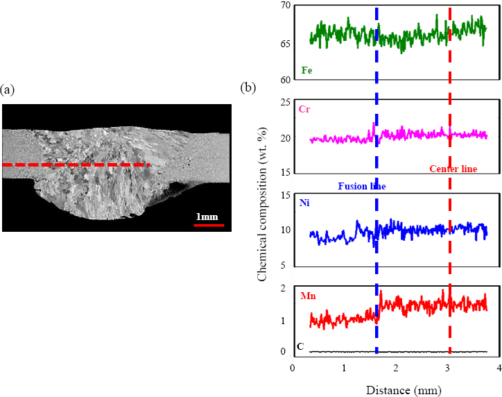
Fig.┬Ā2
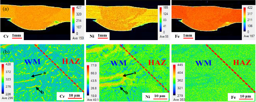
Table┬Ā2
| C | Mn | Ni | Cr | Si | Fe | |
|---|---|---|---|---|---|---|
| a-dendrite core | 0.08 | 2.4 | 9.7 | 18.3 | 0.32 | 69.2 |
| b-interdendritic region | 0.1 | 1.5 | 3.5 | 26.0 | 0.4 | 68.5 |

3.2 Mechanical properties of the GTA weld
3.2.1 Hardness properties of the GTA weld

3.2.2 Tensile properties of the GTA weld at room and cryogenic temperature
Fig.┬Ā7

Fig.┬Ā8


4. Conclusion
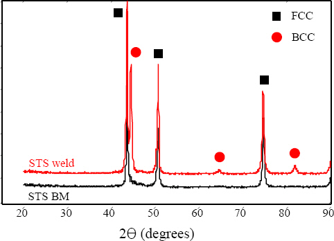
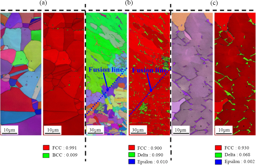
1) Austenitic and ╬┤-ferrite coexisted in the weld of STS 304 using STS 308L filler. 7% of ╬┤-ferrite was formed in the interdendritic region of columnar dendrites grown in one direction from the grains of the HAZ near the fusion line by welding heat.
2) The reason that the average hardness of the WM is lower than that of the STS 304 BM is that the grain size of the BM is finer than that of the columnar grain of the WM. The HAZ near the fusion line has higher hardness than the BM because of the presence of local ╬Ą-martensite and the formation of carbide.
3) Regardless of the change in tensile test temperature (298 K - 77 K), since all the GTA welds showed lower tensile properties than the STS 304 BM, tensile fracture of all the welds occurred at the centerline of the WM. However, the STS 304 weld using STS 308L filler showed excellent cryogenic tensile properties compared to those at room temperature as with the STS 304 BM.
4) The improvement of cryogenic tensile properties was attributed to the fact that deformation twin and martensite phase transformation dominantly occurred. However, since the elongation is reduced in the cryogenic GTA weld, the main strengthening mechanism is considered to be the phase transformation of deformation-induced martensite.
 PDF Links
 PubReader
 ePub Link
 Full text via DOI
 Download Citation
 Print
Print


