1. Introduction
Cowl Cross Bar (CCB) system is one of the most critical automotive components, and its main function is to support man-machine interaction control equipment and enhance the strength of the car body. During its fabrication process, gas metal arc welding (GMAW), which is one high efficiency and steady joining process, is often used to connect the main pipes and the various types of functional brackets. However, welding-induced deformation always occurs inevitably due to uneven thermal expansion and shrinkage of welded metal in the welding process. It not only reduces the dimensional accuracy of the welded structure but also increases manufacturing cost due to additional post-weld correction treatment. Therefore, accurate and efficient prediction and control of welding deformation in the design stage is an important way to improve work efficiency and ensure product quality.
Up to now, the development of welding deformation prediction methods has mainly gone through the following important stages. In the first stage, experimental measurements and empirical formulas are usually used to determine the characteristics of welding distortion. Verhaeghe
1) conducted a comprehensive review on various approximate formulas to calculate the most typical welding distortion including longitudinal shrinkage, transverse shrinkage, and angular distortion. However, these empirical formulas only captured the distortion tendency of specific welding methods, materials, and welded structures. And they could not predict the value of welding deformation accurately and quantitatively.
With the development of advanced computers and the improvement of numerical analysis theory, numerical simulation technologies based on the finite element method (FEM) were applied to predict the welding deformation in the second stage. In the 1970s, the thermo-elastic-plastic finite element method (TEP-FEM) was first proposed to simulate the welding process and calculate welding residual stresses and distortions by Ueda et al.
2). Later, the effectiveness and accuracy of the TEP-FEM were also proved by other researchers
3-6). Venkatkumar et al.
3) presented the sequentially coupled thermo-mechanical FEM simulation to predict temperature distribution, residual stress, and distortion in a welded 304 stainless steel plate. Manurung et al.
5) developed a 3D TEP-FEM model to investigate the effect of welding sequence on the angular distortion during a multipass welding process. Meanwhile, a series of experiments were also conducted to validate the simulation results. Velaga et al.
6) compared the weld characteristics between the longitudinal seam and circumferential butt weld joints of cylindrical components by using TEP-FEM simulation and experimental validation. Currently, the TEP-FEM is widely accepted to accurately model the welding process and capture temperature or stress-strain fields for various welded structures. However, for large-scale and complex structures, it isnŌĆÖt an applicable computational approach to predict welding deformation due to high nonlinearity and excessive computing time.
In the third stage, an elastic FEM analysis based on inherent strain theory
7) was proposed to solve welding distortion problems with a short computational time. The inherent strain that exists in the welded joint is considered as the main source of generating welding residual stress and distortion
8). If the inherent strain value is known, the welding-induced deformation can be estimated using the inherent strain method (ISM). However, there is no such operation to directly input inherent strain as an initial load in commercial FEM analysis software. Since then, researchers have made great efforts to solve this difficulty. Based on the different problem-solving ideas, the ISM can be divided into two types in the field of welding distortion prediction: (1) inherent deformation method; (2) equivalent thermal strain method.
The inherent deformation method has been frequently used to predict welding distortion of large-scale and complex welded structures. Four fundamental inherent deformation components are calculated by integrating the longitudinal inherent strain (
╬Ąlongitudinalinherent) and transverse inherent strain (
╬Ątransverseinherent) distributed on the cross- section through thickness direction according to the following equations
9,10).
where ╬┤longitudinal* and ╬┤transverse* are the inherent deformation in the longitudinal and transverse directions, ╬Ėlongitudinal* and ╬Ėtransverse* are the nherent bending deformation in the longitudinal and transverse directions, respectively. h is the thickness of the welded structures.
Then these obtained equivalent loads are assigned to the elastic FEM model to predict welding deformation of various types of welded joints. For example, Deng et al.
11) precisely predicted welding distortion for large welded structures using the inherent deformation method with experimental verification. Wang et al.
12) reported that an elastic FEM analysis based on inherent deformation theory and interface element is an effective and practical computational approach for welding distortion prediction in the fabrication of large-scale welded offshore structures. Moreover, Wang et al.
13) employed an inherent deformation method to evaluate welding distortion of the spherical welded structure produced by multi welding lines within a very short computing time.
On the other hand, the problem-solving idea of the equivalent thermal strain method is that the inherent strain is directly entered as the equivalent thermal strain to the FEM model. Because the equivalent thermal strain can also be transferred into the product of artificial thermal expansion coefficient (αartificial) and artificial temperature gradient (ΔT), as shown in Eq. (5).
where ╬Ąinherent and ╬Ąequivalent are defined as inherent strain and equivalent thermal strain, respectively.
Based on the above principle, Ha et al.
14) proposed a new kind of thermal distortion analysis method (SDB method) to predict welding distortion. In their study, a shell element model is assigned with a constant artificial thermal expansion coefficient and linear temperature gradient to simulate the shrinkage behavior near the weld. Later, the feasibility and accuracy of the SDB method were also verified in research results presented by Lee et al.
15). Moreover, Kim et al.
16) proposed a simplified thermal strain-based method with composite shell elements to investigate welding deformation of T-joint fillet welds. In their work, experiments and 3D TEP-FEM analysis were also conducted to verify the accuracy of the proposed ISM method.
From the above, the ISM analysis has been proved that has the ability to accurately predict welding distortion in various types of welded joints and large-scale welded structures within a short computing time. However, in the last two decades, a large number of published papers focused mainly on the improvement and application of the inherent deformation method. Related reports on using equivalent thermal strain methods to solve the problems of welding deformation are rare.
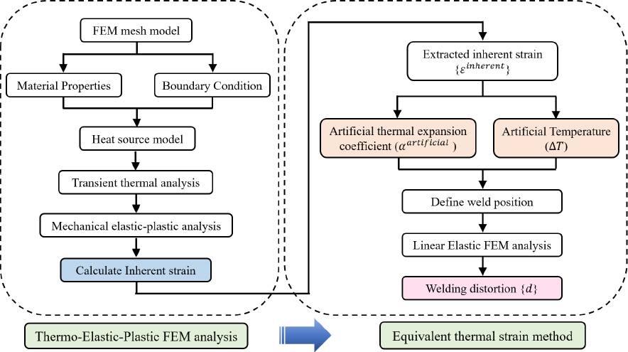
Thus, in this study, an equivalent thermal strain method was developed to predict the welding distortion induced by multi-seam welding in a welded pipe structure. The general computation procedure of the proposed welding deformation prediction method is illustrated in
Fig. 1. Firstly, a full 3D TEP-FEM numerical simulation was conducted to extract the value of inherent strain that occurred in a welded joint quantitatively. Secondly, according to the concept of Eq.(5), the inherent strain is directly assigned to an elastic FEM model for predicting the welding-induced distortion. Moreover, a series of welding experiments were also performed to confirm theaccuracy of simulation models.
Fig.┬Ā1
Computation procedure of the proposed welding deformation prediction method
2. Welding experiment
Fig. 2 shows a typical CCB automotive component design, where various brackets are joined to the left main pipe using the multi-seam GMAW process. And the welds comprise two basic patterns: longitudinal seam (L-seam) and circumferential seam (C-seam). During the assembly process, large welding deformation often occurs in the main pipe structure. Thus, to simplify the welding experiments, brackets are ignored and only the pipe component is heated by a welding arc with the filler metal.
Fig.┬Ā2
Cowl Cross Bar (CCB) system and its welding details during assembly

To confirm the validity and accuracy of the following simulation models, a series of experiments were carried out and the predicted welding distortions are compared with the measured results. In this experiment, a numerical control automatic welding system to was designed perform L-seam and C-seam welding of a pipe, as shown in
Fig. 3. The outer diameter, length, and thickness of the welded specimen are 850mm, 54mm, and 2mm, respectively. The material is low carbon steel STKM 13B. And the welding parameters of the L-seam and C-seam used in our experiments are identical and are presented in
Table 1. The specific details of the welding experiment can be found in the previous study presented by Wu et al.
17). A series of GMAW experimental specimens with different weld seams are illustrated in
Fig. 4.
Table┬Ā1
|
Parameter |
Welding voltage |
Welding current |
Welding speed |
Efficiency |
|
Value |
16.2 V |
131 A |
0.5 m/min |
0.65 |
Fig.┬Ā3
Numerical control automatic welding system
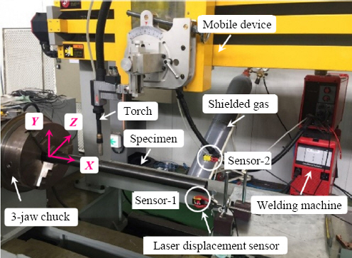
Fig.┬Ā4
A series of GMAW experimental specimens

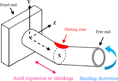
During L-seam and C-seam welding process, local expansion and shrinkage of welded pipe in the axial, circumferential, and thickness direction could occur. Among them, due to a large gradient of axial shrinkage in heating and non-heating zones, a serious bending distortion will be produced in a long pipe, as shown in
Fig. 5. Other deformations are relatively small can be ignored, so only welding-induced bending distortion was investigated in this study.
Fig.┬Ā5
Welding-induced bending distortion in a long pipe
To measure the welding-induced bending distortion, laser displacement sensors are utilized to record the history of the free end displacement in a welded pipe, as shown in
Fig. 3. Two sensors are set in orthogonal directions to measure the displacements in Y-axis and Z-axis coordinates, respectively. Meanwhile, the random errors of experiments can be minimized by calculating the mean of multiple measured values.
4. Elastic FEM analysis
After the inherent strain of L-seam and C-seam welded joints has been obtained by using the developed TEP-FEM analysis, the residual distortion produced by welding can be computed by a linear elastic FEM analysis using the known inherent strain as an input load. To develop a method to apply the strain as an external load to the FEM model, the obtained inherent strain was transformed into an equivalent thermal strain, i.e., an orthotropic thermal expansion coefficient and temperature gradient, as shown in Eq.(10).
where ╬▒iartificial represents the artificial coefficient of thermal expansion in the ith direction in the coordinate system considering the features of the anisotropic distribution of inherent strain.
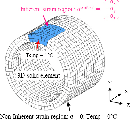
In the elastic FEM model, a 3D-solid element was adopted. The artificial temperature of the nodes within the region of inherent strain is taken as 1Ōäā, while all other nodes are set to zero. Furthermore, an orthotropic artificial thermal expansion coefficient with a constant negative value was assigned to all the elements of the inherent strain zone for effectively simulating the shrinkage behavior during the cooling process of welding. as shown in
Fig. 11. The unit thermal load of each weld was activated step by step and a static equilibrium analysis was performed to calculate residual deformation induced by multi-seam welding. Because the proposed ISM method is an elastic static analysis process, it can save most of the computational time compared with the TEP-FEM simulation.
Fig.┬Ā11
Schematics of mechanism of equivalent thermal strain method
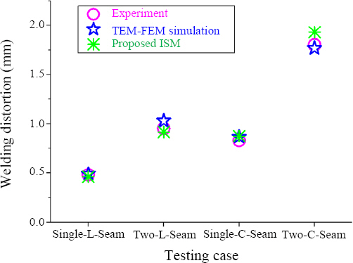
In this present study, two testing cases, i.e., simple welded joints and multi-seam welded structures, are performed to demonstrate the accuracy of the proposed equivalent thermal strain method. For the simple welded joints, the maximum bending distortion resulting from a single seam and two seams welding obtained by experiment, TEP-FEM simulation, and the proposed ISM are compared in
Fig. 12. The results from
Fig. 12 discovered that the discrepancy between measurement data and numerical simulation results is acceptable. Thus, the proposed ISM can be used to accurately predict welding distortion. However, it should be noted that the time-saving advantages of the proposed ISM arenŌĆÖt particularly prominent in simple welded joints.
Fig.┬Ā12
Comparison of maximum bending distortion in simple welded joints among experiment, TEPFEM simulation, and proposed ISM
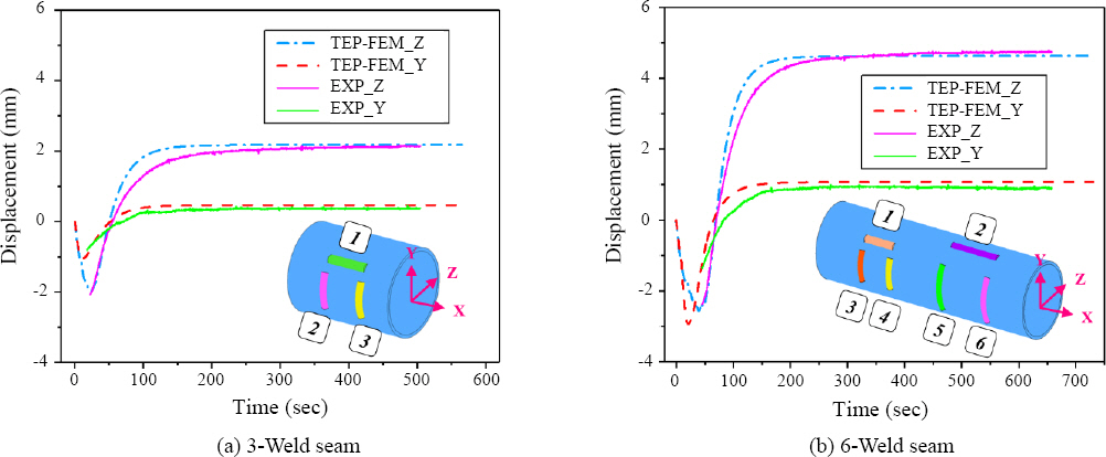
To further demonstrate the accuracy of the proposed ISM, it was also used to investigate the welding distortion of multi-seam welded structures.
Table 2 shows the comparison of the maximum bending distortion among experiment, TEP-FEM, and proposed ISM in the multi-seam welded specimens. Very good consistency is observed in
Table 2, and the efficiency and accuracy of this proposed ISM are validated again.
Table┬Ā2
Maximum bending distortion of multi-seam welded structures
|
Case |
Experimental data |
TEP-FEM simulation |
Proposed ISM |
|
d_y (mm) |
d_z (mm) |
d_y (mm) |
d_z (mm) |
d_y (mm) |
d_z (mm) |
|
3-Weld-Seams |
0.378 |
2.108 |
0.473 |
2.188 |
0.302 |
2.054 |
|
6-Weld-Seams |
0.901 |
4.739 |
1.087 |
4.648 |
0.899 |
4.425 |
For complex and large-scale multi-seam welding, the computational time of the TEP-FEM simulation and proposed ISM is also compared in
Table 3. Generally, compared with TEP-FEM simulation, the computing efficiency of the proposed ISM can be increased by about 50 times. That is because that the complex nonlinear elastic-plastic behavior of the welding process isnŌĆÖt taken into consideration. Especially for more welds, the advantage of computational efficiency is more significant.
Table┬Ā3
Comparison of computational time between TEP- FEM simulation and proposed ISM
|
Case |
Computational time (min) |
|
TEP-FEM simulation |
Proposed ISM |
|
3-Weld-Seams |
223 |
3.8 |
|
6-Weld-Seams |
466 |
8.8 |


 PDF Links
 PubReader
 ePub Link
 Full text via DOI
 Download Citation
 Print
Print


