


1. ņä£ ļĪĀ
ļ░£ņé¼ņ▓┤ ļ¬ĖĒåĄņ£╝ļĪ£ ņØ┤ņÜ®ļÉśļŖö ļ░ĢĒīÉ ņøÉĒåĄĒśĢ ĻĄ¼ņĪ░ļ¼╝ņØĆ ļ╣äĒ¢ē ņŗ£ ņé¼Ļ▒░ļ”¼ ņ”ØļīĆļź╝ ņ£äĒĢ£ Ļ▓Įļ¤ēĒÖöļĪ£ ņÖĖĒö╝ņØś ļæÉĻ╗śļź╝ Ļ░Éņåīņŗ£ĒéżĻ│Ā ņØ┤ņŚÉ Ļ░ÉņåīĒĢ£ Ļ░Ģņä▒ņØä ļ│┤Ļ░ĢĒĢśĻĖ░ ņ£äĒĢ┤ ļ│┤Ļ░Ģņ×¼ļź╝ ņÜ®ņĀæĒĢ£ļŗż. ļ│┤Ļ░Ģņ×¼ ņÜ®ņĀæ ņŗ£ ņÜ®ņ£ĄļČĆņØś ņłśņČĢņŚÉ ņØśĒĢ┤ ņÜ®ņĀæ ļ│ĆĒśĢĻ│╝ ņ×öļźśņØæļĀźņØ┤ ļ░£ņāØĒĢśļ®░1-3) ņĪ░ļ”Į ļČłļ¤ē ļ░Å Ļ│ĄļĀź Ļ░ĆņŚ┤ļĪ£ ņØĖĒĢ£ ļÆżĒŗĆļ”╝Ļ│╝ ņóīĻĄ┤ņØś ļ░£ņāØņØä Ļ░Ćņżæņŗ£Ēé©ļŗż.
ņÜ®ņĀæ ļ│ĆĒśĢĻ│╝ ņ×öļźśņØæļĀźņØä ņśłņĖĪĒĢśĻĖ░ ņ£äĒĢ£ ĒĢ┤ņäØ ņżæ 3ņ░©ņøÉ ņŚ┤Ēāäņåīņä▒ļ▓ĢņØĆ Ļ│╝ļÅäĒĢ£ Ļ│äņé░ ņŗ£Ļ░äĻ│╝ ļ¬©ļŹĖ ļīĆĒśĢĒÖöĻ░Ć ņÜöĻĄ¼ļÉśļ»ĆļĪ£ Ļ│Āņ£Āļ│ĆĒśĢļźĀņØä ņØ┤ņÜ®ĒĢ£ Ļ░äņØ┤ ĒĢ┤ņäØļ▓ĢņŚÉ ļīĆĒĢ£ ņŚ░ĻĄ¼Ļ░Ć ļ¦ÄņØ┤ ņ¦äĒ¢ēļÉśņŚłļŗż4).
Ha.ļŖö ņ×¼ļŻīņØś ņŚ┤ĒīĮņ░ĮĻ│äņłśņÖĆ ņēś ņÜöņåī ņāüĒĢśļČĆ ņś©ļÅä ĻĄ¼ļ░░ļź╝ ļČĆņŚ¼ĒĢśņŚ¼ Ļ░üļ│ĆĒśĢņØä ļ¬©ņé¼ĒĢ£ ļ│ĆĒśĢļźĀĻ▓ĮĻ│äļ▓Ģ(SDB)5)ņØä Ļ░£ļ░£ĒĢśņśĆņ£╝ļéś ņŚ┤ĒīĮņ░ĮĻ│äņłśļź╝ ņØ┤ņÜ®ĒĢśļ»ĆļĪ£ ņČöĻ░ĆņĀüņØĖ ņŚ┤ĻĄ¼ņĪ░ĒĢ┤ņäØņØä ņłśĒ¢ēĒĢśĻĖ░ ņ¢┤ļĀĄļŗżļŖö ļŗ©ņĀÉņØ┤ ņ׳ļŗż5-7).
ļ│Ė ņŚ░ĻĄ¼ņŚÉņä£ļŖö ņÜ®ņĀæļČĆ ņēś ņÜöņåīņØś ļŗżņĖĄ ĻĄ¼ņĪ░ ņĀüļČäņĀÉņŚÉ ņ¦üņĀæ Ļ│Āņ£Āļ│ĆĒśĢļźĀņØä ņ×ģļĀźĒĢśļŖö ņ¦üņĀæņ×ģļĀźļ▓ĢņØä ņĀ£ņĢłĒĢśĻ│Ā ļ░ĢĒīÉ ĻĄ¼ņĪ░ļ¼╝ņØś Ļ░üļ│ĆĒśĢ ņśłņĖĪņŚÉ ņĀüņÜ®ĒĢśņśĆļŗż. ļ░ĢĒīÉ ļĀłņØ┤ņĀĆ Ļ▓╣ņ╣śĻĖ░ ņÜ®ņĀæņŚÉ ļīĆĒĢ┤ 3ņ░©ņøÉ ņŚ┤Ēāäņåīņä▒ļ▓ĢņØä ĒåĄĒĢ┤ Ļ│Āņ£Āļ│ĆĒśĢļźĀņØä Ļ│äņé░ĒĢśņśĆņ£╝ļ®░ ļÅÖņØ╝ ņÜ®ņĀæ ņĪ░Ļ▒┤ņ£╝ļĪ£ ņøÉĒåĄĒśĢ ĻĄ¼ņĪ░ļ¼╝ņØś ņøÉņŻ╝ ļ░®Ē¢ź ņÜ®ņĀæļ│ĆĒśĢņØä ņĖĪņĀĢĒĢśņŚ¼ ņŚ┤Ēāäņåīņä▒ļ▓Ģ, ļ│ĆĒśĢļÅäĻ▓ĮĻ│äļ▓Ģ, ņ¦üņĀæņ×ģļĀźļ▓Ģ Ļ▓░Ļ│╝ņÖĆ ļ╣äĻĄÉĒĢśņśĆļŗż.
2. ņÜ®ņĀæļ│ĆĒśĢ Ļ░äņØ┤ ĒĢ┤ņäØļ▓Ģ
2.1 Ļ│Āņ£Āļ│ĆĒśĢļźĀ
Ļ│Āņ£Āļ│ĆĒśĢļźĀņØĆ ņÜ®ņĀæ Ēøä ņŻ╝ļ│ĆļČĆ ĻĄ¼ņåŹņØä ĒĢ┤ņĀ£ĒĢśņŚ¼ļÅä ļé©ņĢäņ׳ļŖö ļ│ĆĒśĢļźĀņØä ņØśļ»ĖĒĢśļ®░ ņŗØ (1)Ļ│╝ Ļ░ÖņØ┤ ļéśĒāĆļé╝ ņłś ņ׳ļŗż.8,9) ņĀäņ▓┤ ļ│ĆĒśĢļźĀņØä ņŗØ (2)ņÖĆ Ļ░ÖņØ┤ ļéśĒāĆļé┤ļ®┤ ņŗØ (1)Ļ│╝ (2)ļź╝ ņØ┤ņÜ®ĒĢśņŚ¼ Ļ│Āņ£Āļ│ĆĒśĢļźĀņØä ņŗØ (3)Ļ│╝ Ļ░ÖņØ┤ Ēæ£ĒśäĒĢĀ ņłś ņ׳ļŗż. ņØ┤ļ¤¼ĒĢ£ Ļ│Āņ£Āļ│ĆĒśĢļźĀņØĆ ņ×öļźśņØæļĀźņØä Ēæ£ĒśäĒĢśļŖöļŹ░ ņé¼ņÜ®ĒĢśļ®░ ņÜ®ņĀæ ļ│ĆĒśĢ ĒĢ┤ņäØņŚÉ ņØ┤ņÜ®ĒĢĀ ņłś ņ׳ļŗż. ņÜ®ņĀæņŚÉņä£ Ēü¼ļ”ĮņŚÉ ņØśĒĢ£ ļ│ĆĒśĢņØĆ ļāēĻ░ü ņŗ£Ļ░äņØ┤ Ēü¼ļ”ĮņØ┤ ļ░£ņāØĒĢĀ ļ¦īĒü╝ ņČ®ļČäĒĢśņ¦Ć ņĢŖņĢä ņāØļץĒĢĀ ņłś ņ׳ļŗż2).
ņŚ¼ĻĖ░ņä£ ╬Ą : ņĀäņ▓┤ ļ│ĆĒśĢļźĀ, ╬Ą* : Ļ│Āņ£Ā ļ│ĆĒśĢļźĀ, ╬Ąe : Ēāäņä▒ ļ│ĆĒśĢļźĀ, ╬Ąp : ņåīņä▒ ļ│ĆĒśĢļźĀ, ╬Ąth : ņŚ┤ ļ│ĆĒśĢļźĀ, ╬Ąph : ņāüļ│ĆĒā£ņŚÉ ņØśĒĢ£ ļ│ĆĒśĢļźĀ, ╬Ąc : Ēü¼ļ”ĮņŚÉ ņØśĒĢ£ ļ│ĆĒśĢļźĀ
Fig. 1ņŚÉņä£ ņÜ®ņĀæļČĆ ļāēĻ░ü Ļ│╝ņĀĢņØś ņØæļĀź-ļ│ĆĒśĢļźĀ ņäĀļÅäļź╝ ļéśĒāĆļé┤ņŚłļŗż. ņÜ®ņĀæļČĆ ļāēĻ░üņ£╝ļĪ£ ņŚ┤Ļ│╝ ņāüļ│ĆĒā£ņŚÉ ņØśĒĢ£ ļ│ĆĒśĢņØ┤ ļ░£ņāØĒĢśļ®┤ ņŻ╝ļ│Ć ĻĄ¼ņåŹņŚÉ ļö░ļØ╝ ņØæļĀź ĒÅēĒśĢņØ┤ ņØ┤ļŻ©ņ¢┤ņ¦ĆļÅäļĪØ Ēāäņåīņä▒ļ│ĆĒśĢņØ┤ ļ░£ņāØĒĢśņŚ¼ ņĄ£ņóģņĀüņ£╝ļĪ£ ņĀÉ AĻ░Ć ļÉ£ļŗż. ļö░ļØ╝ņä£ Ēāäņåīņä▒ĒĢ┤ņäØņŚÉņä£ Ļ│Āņ£Āļ│ĆĒśĢļźĀ(╬Ą*EP)ņØĆ ņŚ┤Ļ│╝ ņāüļ│ĆĒā£ņŚÉ ņØśĒĢ£ ļ│ĆĒśĢļźĀļĪ£ Ēæ£ĒśäĒĢĀ ņłś ņ׳Ļ│Ā ņØ┤ļź╝ ņÜ®ņĀæļČĆņŚÉ ņ×ģļĀźĒĢśņŚ¼ ņÜ®ņĀæ ļ│ĆĒśĢņØä ļ¬©ņé¼ĒĢĀ ņłś ņ׳ļŗż. ņØ┤ļŖö ņŗØ (4)ņÖĆ Ļ░ÖņØ┤ ņāüļ│ĆĒā£ņŚÉ ņØśĒĢ£ ļ│ĆĒśĢņØä ĒżĒĢ©ĒĢ£ ņŚ┤ĒīĮņ░ĮĻ│äņłś(╬▒mod)ļź╝ ņĄ£ļīĆ ļÅäļŗ¼ņś©ļÅäļČĆĒä░ ņāüņś©Ļ╣īņ¦Ć ņĀüļČäĒĢśņŚ¼ Ļ│äņé░ĒĢ£ļŗż7).

2.2 ļ│ĆĒśĢļÅäĻ▓ĮĻ│äļ▓Ģ(Strain as Direct Boundary, SDB)
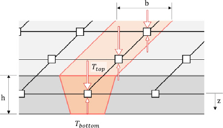
Fig. 2ņŚÉ ņÜ®ņĀæļČĆņØś Ļ│Āņ£Āļ│ĆĒśĢļźĀ(╬Ą*EP)ņØä ņÜ®ņĀæļČĆ ņĀłņĀÉ ņāüļČĆņÖĆ ĒĢśļČĆņŚÉ ļŗżļźĖ Ļ░Ćņāüņś©ļÅäņÖĆ ņŚ┤ĒīĮņ░ĮĻ│äņłśļź╝ ņ×ģļĀźĒĢśņŚ¼ Ļ░üļ│ĆĒśĢņØä ļ¬©ņé¼ĒĢśļŖö ļ│ĆĒśĢļÅäĻ▓ĮĻ│äļ▓ĢņŚÉ ļīĆĒĢ┤ ļéśĒāĆļé┤ņŚłļŗż. ņÜ®ņĀæļČĆ ņś©ļÅäļŖö ņŗØ (5), (6)ņÖĆ Ļ░ÖņØ┤ ņÜ®ņĀæļČĆ ļŗ©ļ®┤ņØś ņŚ┤ņśüĒ¢źļČĆ ĒśĢņāüņØä ļæÉĻ╗ś ļ░®Ē¢źņ£╝ļĪ£ ņĀüļČäĒĢśņŚ¼ Ļ│äņé░ĒĢ£ļŗż5-7).
ņŚ¼ĻĖ░ņä£ Ttop : ņāüļČĆ Ļ░Ćņāüņś©ļÅä, Tbottom : ĒĢśļČĆ Ļ░Ćņāüņś©ļÅä, b : ņŚ┤ņśüĒ¢źļČĆ ļäłļ╣ä, h : ļ¬©ņ×¼ ļæÉĻ╗ś
2.3 ņ¦üņĀæņ×ģļĀźļ▓Ģ(Direct apply Inherent Strain, DIS)
ļ│Ė ņŚ░ĻĄ¼ņŚÉņä£ ņĀ£ņĢłĒĢ£ ņ¦üņĀæņ×ģļĀźļ▓ĢņØĆ Fig. 3Ļ│╝ Ļ░ÖņØĆ ņēś ņÜöņåīņØś ļæÉĻ╗ś ļ░®Ē¢ź ļŗżņĖĄ ĻĄ¼ņĪ░ ņĀüļČäņĀÉņŚÉ Ļ│Āņ£Āļ│ĆĒśĢļźĀņØä ņ×ģļĀźĒĢśņŚ¼ ņÜ®ņĀæļ│ĆĒśĢņØä ļ¬©ņé¼ĒĢśļŖö ļ░®ņŗØņØ┤ļŗż. Ļ░ü ņĀüļČäņĀÉņØś Ļ│Āņ£Āļ│ĆĒśĢļźĀņØĆ ņÜ®ņĀæļČĆ ļŗ©ļ®┤ ņŚ┤ņśüĒ¢źļČĆņØś ĒśĢņāüņØä ņĀüļČäĒĢ£ Ļ░ÆņŚÉ ņŗØ (4)ņŚÉņä£ Ļ│äņé░ĒĢ£ Ļ│Āņ£Āļ│ĆĒśĢļźĀņØä Ļ│▒ĒĢśņŚ¼ Ļ│äņé░ĒĢśļ®░ ļŗżņØī ņŗØ (7), (8)Ļ│╝ Ļ░ÖņØ┤ Ļ│äņé░ ĒĢĀ ņłś ņ׳ļŗż.
(7)
(8)
ņŚ¼ĻĖ░ņä£╬Ąiweld : iļ▓łņ¦Ė ņĖĄ ņÜ®ņĀæļČĆ ņĀüļČäņĀÉ Ļ│Āņ£Āļ│ĆĒśĢļźĀ, ╬Ąibase : iļ▓łņ¦Ė ņĖĄ ļ¬©ņ×¼ļČĆ ņĀüļČäņĀÉ Ļ│Āņ£Āļ│ĆĒśĢļźĀ, ╬Ą*EP : Ļ│Āņ£Āļ│ĆĒśĢļźĀ b : ņŚ┤ņśüĒ¢źļČĆ ļäłļ╣ä, h : ļ¬©ņ×¼ ļæÉĻ╗ś

3. ĒÅēĒīÉ Ļ▓╣ņ╣śĻĖ░ ņÜ®ņĀæ ņŗ£ĒŚś
3.1 ĒśĢņāü ļ░Å ņÜ®ņĀæ ņĪ░Ļ▒┤
Ļ│Āņ£Āļ│ĆĒśĢļźĀ Ļ│äņé░ ļ░Å ņŚ┤ņøÉ ļ¬©ļŹĖ ņäżĻ│äļź╝ ņ£äĒĢ┤ sus304 ĒīÉ ļĀłņØ┤ņĀĆ Ļ▓╣ņ╣śĻĖ░ ņÜ®ņĀæņØä Fig. 4ņÖĆ Ļ░ÖņØ┤ ņ¦äĒ¢ēĒĢśņśĆļŗż. ņāüĒīÉņØĆ 200├Ś200 mmņŚÉ ļæÉĻ╗śļŖö 2, 2.6 mmņØ┤ļ®░ ĒĢśĒīÉņØĆ 200├Ś50 mmņŚÉ ļæÉĻ╗śļŖö 2 mmņØ┤ļŗż. ņāüĒīÉĻ│╝ ĒĢśĒīÉņØś ļæÉĻ╗śļŖö ļ░£ņé¼ņ▓┤ ļ¬ĖĒåĄ ļæÉĻ╗śļź╝ ļ░śņśüĒĢśņśĆļŗż.

ļĀłņØ┤ņĀĆ ņÜ®ņĀæ ņŚ┤ņøÉņØĆ Table 1Ļ│╝ Ļ░ÖņØ┤ ņāüĒīÉ ļæÉĻ╗śņŚÉ ļö░ļØ╝ 2 mmļŖö 3600 W, 2.6 mmļŖö 3800 Wļź╝ 2 m/min ņåŹļÅäļĪ£ 5 mm Ļ▒░ļ”¼ņŚÉņä£ ņłśņ¦üļ░®Ē¢źņ£╝ļĪ£ ņÜ®ņĀæĒĢśņśĆņ£╝ļ®░ solid state ļĀłņØ┤ņĀĆņØś ņŚ░ņåŹĒīīļź╝ ņØ┤ņÜ®ĒĢśņśĆļŗż. ļ│┤ĒśĖĻ░ĆņŖżļŖö NŌééļź╝ ņØ┤ņÜ®ĒĢśĻ│Ā ņ£Āļ¤ēņØĆ 25l/minļĪ£ ņÜ®ņĀæĒĢśņśĆļŗż.
3.2 3ņ░©ņøÉ ņŚ┤Ēāäņåīņä▒ļ▓Ģ ņÜ®ņĀæĒĢ┤ņäØ
ņŚ┤ņøÉ ļ¬©ļŹĖ ņäżĻ│ä ļ░Å Ļ│Āņ£Āļ│ĆĒśĢļźĀ Ļ│äņé░ņØä ņ£äĒĢ┤ Fig. 5ņÖĆ Ļ░ÖņØ┤ ļČĆļČä ļ¬©ļŹĖņØś 3ņ░©ņøÉ ņŚ┤Ēāäņåīņä▒ ņÜ®ņĀæĒĢ┤ņäØņØä ņØ┤ņÜ®ĒĢśņŚ¼ Fig. 6Ļ│╝ Ļ░ÖņØ┤ ņĄ£ļīĆ ļÅäļŗ¼ņś©ļÅä ļČäĒżĻ░Ć ņÜ®ņ£ĄņĀÉ ņś©ļÅä10) ņØ┤ņāüņØ┤ ļÉśļÅäļĪØ ņŚ┤ņøÉ ļ¬©ļŹĖņØä ņäżĻ│äĒĢ£ Ēøä ņ×¼Ļ▓░ņĀĢ ņś©ļÅä ņØ┤ņāü ļČäĒżļź╝ ņŚ┤ņśüĒ¢źļČĆļĪ£ ĒĢśņŚ¼ Ļ│Āņ£Āļ│ĆĒśĢļźĀņØä Ļ│äņé░ĒĢśņśĆļŗż2,5).

Fig.┬Ā6
Cross-section after laser lab welding test and distribution of fusion zone on finite elements model

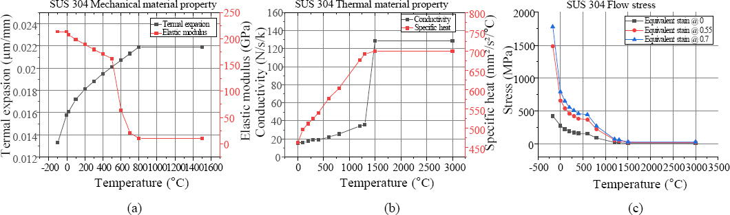
Sus304ņØś ĻĖ░Ļ│äņĀü, ņŚ┤ņĀü ļ¼╝ņä▒ņ╣śņÖĆ ņ£ĀļÅÖņØæļĀźņØĆ Fig. 7ņŚÉ ļéśĒāĆļé┤ņŚłņ£╝ļ®░ ļ░ĆļÅäļŖö 7.9 g/cm3 ĒæĖņĢäņåĪ ļ╣äļŖö 0.3ņ£╝ļĪ£ ĒĢśņśĆļŗż. ņāüļ│ĆĒā£ņÖĆ ņÜ®ņ£Ą ĻĖłņåŹņØś ĒØÉļ”äņŚÉ ņØśĒĢ£ ņśüĒ¢źņØĆ ļ¼┤ņŗ£ĒĢśņśĆĻ│Ā ņāüņÜ® ņĮöļō£ņØĖ marc2021.4ļź╝ ņØ┤ņÜ®ĒĢśņŚ¼ ņŚ┤Ēāäņåīņä▒ļ▓Ģ ĒĢ┤ņäØņØä ņłśĒ¢ēĒĢśņśĆļŗż.
Fig.┬Ā7
Material properties of stainless steel SUS 304 based on temperature, (a) mechanical material property, (b) thermal material property, (c) flow stress
ņ×ģņŚ┤ ļ¬©ļŹĖņØĆ PavelicŌĆÖs disc ļ¬©ļŹĖņØä ņØ┤ņÜ®ĒĢ£ Ēæ£ļ®┤, ļČĆĒö╝ ņŚ┤ņĀäļŗ¼ ļ¬©ļŹĖņØä ņØ┤ņÜ®ĒĢśņśĆņ£╝ļ®░ heat fluxļŖö ņŗØ (9)ņŚÉ ļéśĒāĆļé┤ņŚłĻ│Ā Table 2ņŚÉ Ļ▓░ņĀĢļÉ£ ņŚ┤ņøÉ ļ¬©ļŹĖņØś ņé¼ņ¢æņØä ļ│┤ņśĆļŗż11).
ņŚ¼ĻĖ░ņä£ q : ļŗ©ņ£ä ļ®┤ņĀüļŗ╣ heat flux, Q : ņĀüņÜ®ļÉ£ ņŚ┤ļ¤ē(Q = ╬ĘVI, ╬ĘļŖö ĒÜ©ņ£©, VļŖö ņĀäņĢĢ, IļŖö ņĀäļźś), r : disc ļ░śĻ▓Į, z : ņÜ®ņĀæĻ▓ĮļĪ£ ļ░®Ē¢ź ĻĄŁļČĆ ņóīĒæ£, x : ņÜ®ņĀæĻ▓ĮļĪ£ ņĀæņäĀļ░®Ē¢ź ĻĄŁļČĆ ņóīĒæ£
3.3 Ļ│Āņ£Āļ│ĆĒśĢļźĀ Ļ│äņé░
Sus304ņØś Ļ▓ĮņÜ░, ņāüņś©ņ£╝ļĪ£ ļāēĻ░ü ņŗ£ ļ¦łļź┤ĒģÉņé¼ņØ┤ĒŖĖ ļČĆĒö╝ ļČäļźĀņØ┤ 0.5% ņØ┤ĒĢśļĪ£ ņāüļ│ĆĒā£Ļ░Ć Ēü¼Ļ▓ī ļéśĒāĆļéśņ¦Ć ņĢŖļŖö Ļ░ĢņóģņØ┤ļ»ĆļĪ£12) ņŗØ (4)ņŚÉņä£ ņāüļ│ĆĒā£ņŚÉ ņØśĒĢ£ ņśüĒ¢źņØä ņĀ£ņÖĖĒĢśĻ│Ā ņŚ┤ĒīĮņ░ĮĻ│äņłśļź╝ ņś©ļÅäņŚÉ ļö░ļØ╝ ņĀüļČäĒĢśņŚ¼ -0.024ļĪ£ Ļ│Āņ£Āļ│ĆĒśĢļźĀņØä Ļ│äņé░ĒĢśņśĆļŗż.
Fig. 8ņŚÉņä£ ņĄ£ļīĆ ļÅäļŗ¼ņś©ļÅäĻ░Ć ņ×¼Ļ▓░ņĀĢ ņś©ļÅäņØĖ 728Ōäā10,11) ņØ┤ņāüņØĖ ņśüņŚŁņØä ļéśĒāĆļé┤ņŚłņ£╝ļ®░ ņØ┤ļź╝ ņŚ┤ņśüĒ¢źļČĆļĪ£ ņŗØ (5)-(8)ņØä ņØ┤ņÜ®ĒĢśņŚ¼ ļ│ĆĒśĢļÅä Ļ▓ĮĻ│äļ▓ĢņØś Ļ░Ćņāüņś©ļÅäņÖĆ ņ¦üņĀæņ×ģļĀźļ▓ĢņØś Ļ│Āņ£Āļ│ĆĒśĢļźĀņØä Table 3, 4ņÖĆ Ļ░ÖņØ┤ Ļ│äņé░ĒĢśņśĆļŗż.

Table┬Ā3
Virtual temperatures for SDB analysis
| Skin | Stiffener | ||
|---|---|---|---|
| t2.0 Model | Ttop | 0.383 | 0.1746 |
| Tbottom | 0.277 | 0.149 | |
| t2.6 Model | Ttop | 0.446 | 0.111 |
| Tbottom | 0.25 | 0.0375 | |
Table┬Ā4
Inherent strain based for DIS analysis
4. ņøÉĒåĄĒśĢ ĻĄ¼ņĪ░ļ¼╝ņØś ņÜ®ņĀæļ│ĆĒśĢ
4.1 ņøÉĒåĄĒśĢ ĻĄ¼ņĪ░ļ¼╝ ņÜ®ņĀæļ│ĆĒśĢņŗżĒŚś
Fig. 9ņŚÉ ļ│┤ņØĖ ļ░öņÖĆ Ļ░ÖņØ┤ ņĀäņ▓┤ ļåÆņØ┤ 240 mm, ņ¦Ćļ”ä 400 mmņØ┤Ļ│Ā ļæÉĻ╗śĻ░Ć 2, 2.6 mmņØĖ ņÖĖĒö╝ņÖĆ ļ│┤Ļ░Ģņ×¼Ļ░Ć 90┬░ Ļ░äĻ▓®ņ£╝ļĪ£ ļĀłņØ┤ņĀĆ Ļ▓╣ņ╣śĻĖ░ ņÜ®ņĀæļÉ£ ņøÉĒåĄĒśĢ ĻĄ¼ņĪ░ļ¼╝ņØś ņÜ®ņĀæļ│ĆĒśĢ ņŗżĒŚś ļ░Å ĒĢ┤ņäØņØä ņ¦äĒ¢ēĒĢśņśĆļŗż.

ņÜ®ņĀæļČĆļŖö ļ│┤Ļ░Ģņ×¼ ņżæņŗ¼ņØä ĻĖ░ņżĆņ£╝ļĪ£ 15.8 mmņŚÉ ņ£äņ╣śĒĢśļ®░ ļ░öļŗźņŚÉņä£ 40 mmļČĆĒä░ 60 mm ņÜ®ņĀæĒĢ£ Ēøä 40 mm Ļ░äĻ▓®ņ£╝ļĪ£ ņÜ®ņĀæĒĢśņśĆļŗż. ņÜ®ņĀæļČĆ ņé¼ņØ┤ļŖö Ēī©ņŖżļäłļĪ£ Ļ│ĀņĀĢĒĢśņśĆĻ│Ā ņÜ®ņĀæ ņé¼ņ¢æņØĆ ĒÅēĒīÉ Ļ▓╣ņ╣śĻĖ░ ņÜ®ņĀæĻ│╝ ļÅÖņØ╝ĒĢśĻ▓ī ĒĢśņśĆļŗż.
ļ░śĻ▓Į ļ░®Ē¢ź ņÜ®ņĀæ ļ│ĆĒśĢ ņĖĪņĀĢņØĆ SWISS TRIMOS SA ņé¼ņØś Vectra 3D ņé╝ņ░©ņøÉ ņĖĪņĀĢĻĖ░ļź╝ ņØ┤ņÜ®ĒĢśņŚ¼ Fig. 10ņŚÉ ļ│┤ņØĖ ņ£äņ╣śņØś ļ░śĻ▓Į ļ░®Ē¢ź ļ│ĆĒśĢņØä ņĖĪņĀĢĒĢśņśĆļŗż.

4.2 ņøÉĒåĄĒśĢ ĻĄ¼ņĪ░ļ¼╝ ņÜ®ņĀæļ│ĆĒśĢĒĢ┤ņäØ
ņŚ┤Ēāäņåīņä▒ļ▓Ģ, ļ│ĆĒśĢļÅäĻ▓ĮĻ│äļ▓Ģ, ņ¦üņĀæņÜ®ņĀæļ▓ĢņØś ĒĢ┤ņäØ Ļ▓░Ļ│╝ ļ░Å Ļ│äņé░ ņŗ£Ļ░äņØä ļ╣äĻĄÉĒĢśņŚ¼ ĒÜ©ņ£©ņä▒ņØä ĒÅēĻ░ĆĒĢśņśĆļŗż. Fig. 11 (a), (b)ļŖö ņ£Īļ®┤ņ▓┤ ņÜöņåīļĪ£ ĻĄ¼ņä▒ļÉ£ ņŚ┤Ēāäņåīņä▒ ļ¬©ļŹĖņØ┤ļ®░, Ļ│äņé░ ņŗ£Ļ░ä ĒÜ©ņ£©ņØä ņ£äĒĢ┤ ņÜ®ņĀæļČĆļź╝ ņ×æņØĆ ņÜöņåīļĪ£ ĻĄ¼ņä▒ĒĢśĻ│Ā, 1/4 ļ¬©ļŹĖņØä ņØ┤ņÜ®ĒĢśņśĆļŗż. ņŻ╝ļ│Ć ņś©ļÅäņÖĆ ļ¬©ņ×¼ ņ┤łĻĖ░ ņś©ļÅäļŖö 25ŌäāņØ┤ļ®░, ļīĆļźśļŖö 4 W/ŃÄĪŌäāņØ┤Ļ│Ā ņÜ®ņĀæ Ēøä ļāēĻ░ü ņŗ£Ļ░äņØĆ 1ņŗ£Ļ░äņ£╝ļĪ£ ņäżņĀĢĒĢśņśĆļŗż.
Fig.┬Ā11
Geometry property (a) 3D thermal mechanical model - iso view 1, (b) 3D thermal mechanical model - iso view 2, (c) SDB and DIS model

Fig. 11 (c)ļŖö ļ│ĆĒśĢļÅäĻ▓ĮĻ│äļ▓ĢĻ│╝ ņ¦üņĀæņ×ģļĀźļ▓Ģ ļ¬©ļŹĖņØä ļ│┤ņØ┤ļ®░ ņÖĖĒö╝ņÖĆ ļ│┤Ļ░Ģņ×¼ļŖö 10├Ś10 mm ņēś ņÜöņåī, ĒöäļĀłņ×äņØĆ ņ£Īļ®┤ņ▓┤ ņÜöņåīļź╝ ņØ┤ņÜ®ĒĢśņśĆļŗż. ļ¼╝ņä▒ņ╣śļŖö ĒÅēĒīÉ ļ¬©ļŹĖĻ│╝ ļÅÖņØ╝ĒĢśļéś ļ│ĆĒśĢļÅäĻ▓ĮĻ│äļ▓ĢņŚÉņä£ ņŚ┤ĒīĮņ░ĮĻ│äņłśļŖö Ļ│Āņ£Āļ│ĆĒśĢļźĀņØĖ -0.024ļź╝ ņØ┤ņÜ®ĒĢśņśĆļŗż. ļ│ĆĒśĢļÅäĻ▓ĮĻ│äļ▓ĢĻ│╝ ņ¦üņĀæņ×ģļĀźļ▓Ģ ļ¬©ļŹĖ ņÜ®ņĀæļČĆņŚÉ Ļ│äņé░ĒĢ£ Ļ░Ćņāüņś©ļÅäņÖĆ Ļ│Āņ£Āļ│ĆĒśĢļźĀņØä ņ×ģļĀźĒĢśņśĆļŗż. ĒÅēļ®┤ ņŗżĒŚśņØä ĒåĄĒĢ┤ Ļ░Ćņāüņś©ļÅäņÖĆ Ļ│Āņ£Āļ│ĆĒśĢļźĀ Ļ│äņé░ĒĢśņśĆņ£╝ļéś ņŚ┤ņśüĒ¢źļČĆ Ēü¼ĻĖ░Ļ░Ć ņøÉĒåĄĒśĢ ĻĄ¼ņĪ░ļ¼╝ņØś Ļ│ĪļźĀ ļ░śĻ▓ĮņŚÉ ļ╣äĒĢ┤ ļ¦żņÜ░ ņ×æņĢä Ļ│Īļ®┤ņØś ņŚ┤ņśüĒ¢źļČĆņÖĆ ĒśĢņāüņØ┤ ņ£Āņé¼ĒĢśļŗżĻ│Ā Ļ░ĆņĀĢ ĒĢśņśĆļŗż. marc2021.4ļź╝ ņØ┤ņÜ®ĒĢśņŚ¼ Ļ│äņé░ĒĢśņśĆņ£╝ļ®░, Ļ│Āņ£Āļ│ĆĒśĢļźĀ ņ×ģļĀźņØä ņ£äĒĢ┤ user subroutineņØä ņé¼ņÜ®ĒĢśņśĆļŗż.
4.3 ņŗżĒŚśĻ│╝ ĒĢ┤ņäØ ļ╣äĻĄÉ ļ░Å Ļ│Āņ░░
Fig. 12ņŚÉ ņÖĖĒö╝ ļæÉĻ╗ś 2 mm, 2.6 mmņØĖ ļ¬©ļŹĖņŚÉņä£ ņŚ┤Ēāäņåīņä▒ļ▓Ģ, ļ│ĆĒśĢļÅäĻ▓ĮĻ│äļ▓Ģ, Ļ│Āņ£Āļ│ĆĒśĢļÅäļ▓Ģ ļ¬©ļŹĖņØś ļ░śĻ▓Į ļ░®Ē¢ź ļ│Ćņ£ä ļČäĒżļź╝ ļéśĒāĆļāłļŗż.
Fig.┬Ā12
Radial displacement distribution about 2mm skin thickness, (a)~(c) 2mm skin thickness, (d)~(e) 2.6mm skin thickness, (a, d) 3D thermo-elastoplastic model, (b, e) SDB model, (c, f) DIS model
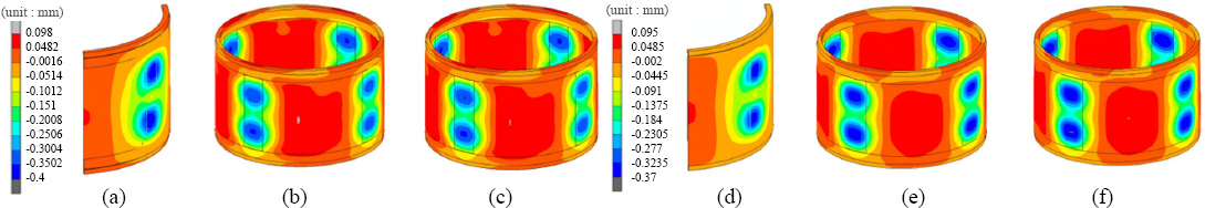
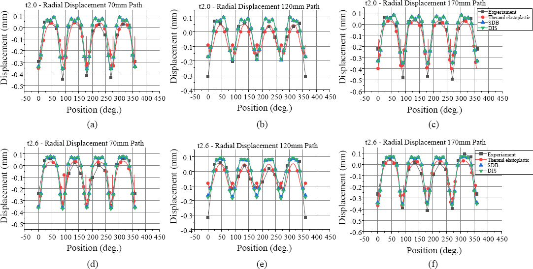
Fig. 13ņŚÉņä£ Ļ░üĻ░üņØś Ļ│äņĖĪ Ļ▓ĮļĪ£ņŚÉņä£ ļ░śĻ▓Į ļ░®Ē¢ź ļ│Ćņ£äĻ░Ć ņ£Āņé¼ĒĢ©ņØä ĒÖĢņØĖĒĢśņśĆņ£╝ļ®░ ņÜ®ņĀæļČĆņØś ņĄ£ņå¤Ļ░Æ ĒÅēĻĘĀĻ│╝ 45┬░, 135┬░, 225┬░, 315┬░ņ£äņ╣ś ņĄ£ļīōĻ░Æ ĒÅēĻĘĀņØä ņŗżĒŚśĻ│╝ ļ╣äĻĄÉĒĢśņŚ¼ Table 5ņŚÉ ņĀĢļ”¼ĒĢśņśĆļŗż. ļīĆļČĆļČäņØś Ļ▓ĮņÜ░ 10% ņØ┤ĒĢś ņ░©ņØ┤ļź╝ ļ│┤ņśĆņ£╝ļéś ņØ╝ļČĆ 10% ņØ┤ņāü ņ░©ņØ┤ļź╝ ļ│┤ņØ┤ļŖö ļČĆļČäņØĆ ņÜ®ņĀæ ņł£ņä£, ņøÉĒåĄĒśĢ ļ▓żļö® Ļ░ĆĻ│Ą ņŗ£ ļ░£ņāØĒĢ£ ņ×öļźśņØæļĀź ļō▒ņØś ņśüĒ¢źņ£╝ļĪ£ ĒīÉļŗ©ļÉ£ļŗż.
Fig.┬Ā13
Experimental and analysis result comparison of radial displacement (a)~(c) 2mm skin thickness, (d)~(e) 2.6mm skin thickness, (a, d) 3D thermo-elastoplastic model, (b, e) SDB model, (c, f) DIS model
Table┬Ā5
Comparison of the difference between max and min of radial displacement
Table 6ņŚÉņä£ Ļ░ü ĒĢ┤ņäØ ļ░®ņŗØņŚÉ ļö░ļźĖ Ļ│äņé░ ņŗ£Ļ░äņØä ļ╣äĻĄÉĒ¢łņØä ļĢī ņŚ┤Ēāäņåīņä▒ļ▓ĢņØ┤ ņ¦üņĀæņ×ģļĀźļ▓ĢņŚÉ ļ╣äĒĢ┤ ņĢĮ 2,160ļ░░ ņĀĢļÅä Ļ│äņé░ ņŗ£Ļ░äņØ┤ ņåīņÜöļÉÉņ£╝ļ»ĆļĪ£ ņ¦üņĀæņ×ģļĀźļ▓ĢņØ┤ ņŚ┤Ēāäņåīņä▒ļ▓ĢņŚÉ ļ╣äĒĢ┤ ĒÜ©ņ£©ņĀüņØĖ Ļ│äņé░ļ░®ņŗØņ×äņØä ĒÖĢņØĖĒĢśņśĆļŗż.
5. Ļ▓░ ļĪĀ
ĒÅēĒīÉ ņÜ®ņĀæņŚÉ ļīĆĒĢ£ ņÜ®ņĀæļČĆ ļŗ©ļ®┤ Ļ┤Ćņ░░Ļ│╝ 3ņ░©ņøÉ ņŚ┤Ēāäņåīņä▒ ĒĢ┤ņäØ ļ¬©ļŹĖņØä ĒåĄĒĢ┤ ņŚ┤ņøÉ ļ¬©ļŹĖ ņäżĻ│äņÖĆ Ļ│Āņ£Āļ│ĆĒśĢļÅäļź╝ Ļ│äņé░ĒĢśņśĆļŗż.
ņēś ņÜöņåīņØś ļŗżņĖĄ ĻĄ¼ņĪ░ ņĀüļČäņĀÉņŚÉ Ļ│Āņ£Āļ│ĆĒśĢļÅäļź╝ ņ¦üņĀæ ņ×ģļĀźĒĢśļŖö ļ░®ļ▓ĢņØä ņĀ£ņĢłĒĢśņŚ¼ ņÜ®ņĀæ ļ│ĆĒśĢņØä ĻĄ¼ĒśäĒĢśņśĆĻ│Ā ĒāĆ ņÜ®ņĀæ ĒĢ┤ņäØ ļ░Å ņŗżĒŚśĻ│╝ ļ╣äĻĄÉĒĢśņŚ¼ ņןļŗ©ņĀÉņØä ĒÅēĻ░ĆĒĢśņśĆļŗż.
ņøÉĒåĄĒśĢ ĻĄ¼ņĪ░ļ¼╝ ņÜ®ņĀæ ņŗżĒŚśņØä ņ¦äĒ¢ēĒĢśņŚ¼ ļ░śĻ▓Į ļ░®Ē¢ź ļ│Ćņ£äļź╝ ņĖĪņĀĢĒĢśņśĆĻ│Ā ņĀ£ņĢłļÉ£ ņ¦üņĀæņ×ģļĀźļ▓ĢĻ│╝ ļ╣äĻĄÉĒĢ£ Ļ▓░Ļ│╝, ņ░©ņØ┤Ļ░Ć ņĢĮ 10% ļé┤ņÖĖļĪ£ ļéśĒāĆļéś ņÜ®ņĀæļ│ĆĒśĢ ņśłņĖĪ ņŗĀļó░ņä▒ņØä ĒÖĢņØĖĒĢśņśĆļŗż.
ņ¦üņĀæņ×ģļĀźļ▓ĢĻ│╝ ņŚ┤Ēāäņåīņä▒ļ▓ĢņØä ļ╣äĻĄÉĒĢśņśĆņØä ļĢī ņ£Āņé¼ĒĢ£ Ļ▓░Ļ│╝ņÖĆ ļ╣ĀļźĖ Ļ│äņé░ņåŹļÅäļź╝ ļ│┤ņ×äņ£╝ļĪ£ ĒÜ©ņ£©ņĀüņØĖ ĒĢ┤ņäØņ×äņØä ĒÖĢņØĖĒĢśņśĆļŗż.
ļ│ĆĒśĢļÅäĻ▓ĮĻ│äļ▓ĢĻ│╝ ļ╣äĻĄÉ ņŗ£ ļÅÖņØ╝ĒĢ£ Ļ▓░Ļ│╝ļź╝ ļ│┤ņśĆņ£╝ļéś ļ│ĆĒśĢļÅäĻ▓ĮĻ│äļ▓ĢņØĆ ņ×¼ļŻīņØś ņŚ┤ĒīĮņ░ĮĻ│äņłśļź╝ ņØ┤ņÜ®ĒĢśĻĖ░ ļĢīļ¼ĖņŚÉ ņÜ®ņĀæĒĢ┤ņäØ Ēøä ņŚ┤ĻĄ¼ņĪ░ĒĢ┤ņäØņØ┤ ņ¢┤ļĀżņøĆņØ┤ ņ׳ņ£╝ļéś ņ¦üņĀæņ×ģļĀźļ▓ĢņØĆ ņÜ®ņĀæ ļ│ĆĒśĢ ĒĢ┤ņäØ Ēøä Ļ│ĄļĀź Ļ░ĆņŚ┤Ļ│╝ Ļ░ÖņØĆ ņŚ░ņåŹņĀüņØĖ ņŚ┤ĻĄ¼ņĪ░ĒĢ┤ņäØņØä ņēĮĻ▓ī ņĀüņÜ®ĒĢĀ ņłś ņ׳ņØä Ļ▓āņ£╝ļĪ£ ĻĖ░ļīĆļÉ£ļŗż.
 PDF Links
 PubReader
 ePub Link
 Full text via DOI
 Download Citation
 Print
Print


