1. Introduction
Electrochemical metallic ion migration (ECM) is known to be one of the contributing causes of intermittent faults in electronic products. Addressing this critical issue, ongoing investigations have successfully unraveled and theoretically elucidated the causes of ECM. Notably, ECM is a phenomenon of short-circuiting that occurs within a printed circuit board (PCB) due to the decrease in insulation resistance between circuits with different polarities, consequently leading to failures in electronic products
1-7). With the recent increase in the high-density fine pitch of electronic products, the frequency of ECM occurrences has been continuously rising. Additionally, as the installation rate of automotive electronics in vehicles increases, ECM-induced failures within these components, used in various safety and convenience devices, have been observed. Moreover, with the rising use of electronic and autonomous vehicles, there is a need to quantitatively evaluate the failure sites and susceptibility of ECM occurrences in the components of eco-friendly vehicles according to usage environments, necessitating efforts in design modifications for mitigation
3-6). As shown in
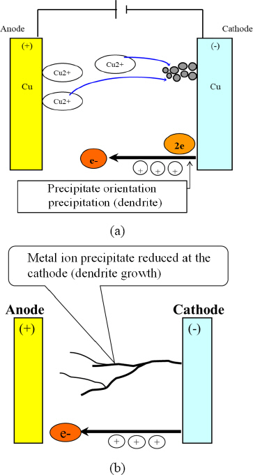
Fig. 1, ECM is a phenomenon where, in the presence of moisture on or within the PCB surface, filamentous dendrites of conductive metal form between circuit patterns of different polarities when voltage or current is applied, causing a short. The necessary conditions for ECM to occur include the presence of electrical carriers such as metallic ions between patterns, moisture to electrolyze and mobilize these ionized metallic ions, and electrical potential applied between two electrodes. The growth rate of dendrites due to ion migration is influenced by various factors, including voltage, relative humidity, temperature, contamination, process, substrate material, metal pattern (electrode) materials, circuit geometry, and the spacing between patterns
1,3-6). ECM can occur in various sites such as the external surface of PCBs, inner layer interfaces, or at the interfaces of solder masks and conformal coating layers. Dendrites form and grow when metal ions, after migrating from the anode, undergo deposition and reduction at the cathode. These dendrites decrease the insulation resistance between two circuits and cause a short. When this short occurs, the dendrites burn, which subsequently leads to the restoration of the original insulation resistance between the circuits. Hence, ECM occurrences in operational environments are difficult to observe directly and are often identified by burnt traces, thereby being considered intermittent faults.
Fig.┬Ā1
Schematic (a) occurrence mechanism of electrochemical ion migration and (b) dendrite growth between electrodes in applied bias voltage
In automotive electronics, a variety of electronic components are used, including chip-type passive components. The usage of chip resistors and multi-layer ceramic chip capacitors (MLCCs) is on the rise. The size of these chip components is continuously decreasing, with applications extending from 3216 Chip (3.2├Ś1.6 mm) parts to even 0402 Chip (0.4├Ś0.2 mm) components. In the case of MLCCs, as the component size decreases, the spacing between the two electrodes further shrinks, leading to observed occurrences of ECM between them. The electrodes of a typical MLCC are made by applying copper (Cu) epoxy, followed by nickel (Ni) plating and tin (Sn) coating for surface treatment. In cases of ECM in MLCCs, the elements Sn, Ni, and Cu, which constitute the electrode surface material, become the main components of the dendrites.
In this study, we used the 1608 MLCC chip components, which are employed in automotive electronic components, to conduct three types of temperature-humidity- bias (THB) tests at 65┬░C/85% R.H., 65┬░C/95% R.H., and 85┬░C/85% R.H, and observed the ECM phenomenon occurring on the surface of MLCC electrodes. The ECM occurrence time was measured for each environmental condition from the three types of THB tests, and the failure occurrence times were compared. To observe dendrite formation, analysis was conducted using an optical microscope, scanning electron microscopy (SEM), and energy dispersive spectroscopy (EDS). Based on these experimental results, a comparative analysis was performed on the susceptibility of MLCC components to ECM under different usage conditions of automotive electronics.
2. Experimental Methods
2.1 MLCC Parts and Coupon Board for Ion Migration Testing
Fig. 2 outlines the specifications for the 1608 MLCC (1.6├Ś0.8 mm (W├ŚD), CL High Capacitance Automotive MLCCs, X7R temperature characteristics, -55 to 125┬░C range, 4.74 ┬ĄF┬▒10% tolerance, Samsung Electro- Mechanics Co. Ltd., Korea) components and PCB pads used in the ECM test. The employed PCB was comprised of FR-4 material with a glass transition temperature (T
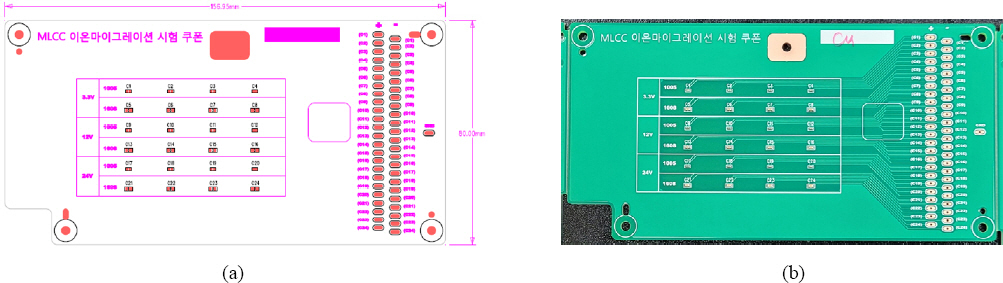
g) of 150┬░C, a thickness of 1.6 mm, and was surface-treated with an organic solderability preservative (OSP). The PCB board (157├Ś80 mm) circuit, as depicted in
Fig. 3, was designed and fabricated to enable the application of power to each MLCC component and to measure resistance in real time. For mounting the MLCC components, the Sn-3.0Ag-0.5Cu (SAC305, Tamura Chemical Co. Ltd., Japan) solder paste was used, and the assembly process was conducted using reflow soldering at a peak temperature of 245┬░C, as shown in
Fig. 3(b).
Fig.┬Ā2
Schematic images of (a) 1608 MLCC component and (b) PCB pad design for MLCC surface mounting

Fig.┬Ā3
Photographs of (a) PCB drwaing design and (b) test coupon board of ECM test
2.2 ECM Testing
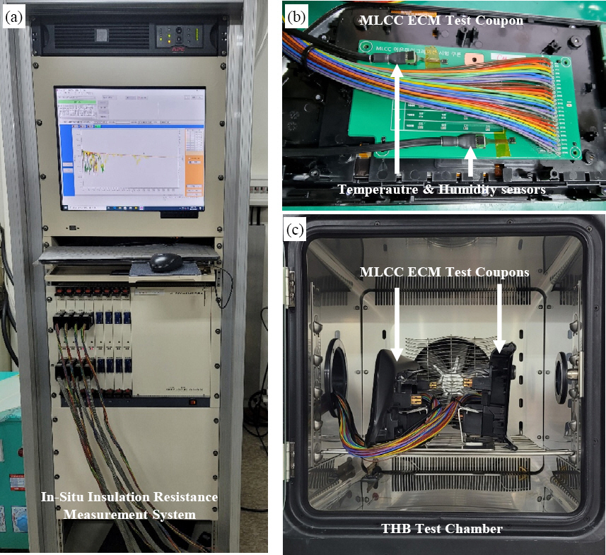
Fig. 4 presents the setup for evaluating the ECM sensitivity of the 1608 MLCC automotive components, employing the THB test.
Fig. 4(a) features the equipment for measuring and recording the resistance of each MLCC component in real-time, every 40 mms, using the NY-IM 1000 (Japan) and SIR-12 system (ETAC Co., Japan).
Fig. 4(b) shows the MLCC-mounted coupon board connected with wires for power application and insulation resistance measurement, and the temperature and humidity sensor attached for real-time monitoring. The utilized temperature and humidity sensor was the Sensirion SHT85 from Sensirion Co. (www.sensirion.com / D1). The three types of THB tests were conducted using a constant temperature and humidity chamber (SH-662 temperature-humidity chamber, Espec Co. Ltd., Japan), as depicted in
Fig. 4(c).
Fig.┬Ā4
Photographs of MLCC ECM test set-up, (a) In-situ insulation resistance measurement system, (b) test vehicle of MLCCs surface mounted board and wire connected for resistance and (c) test vehicles set-up in the TBH chamber
During the ECM tests, three voltages of 3.3, 12.0, and 24.0 V were applied to the MLCC component to compare the effect of voltage on the acceleration of ECM occurrence. To compare ECM sensitivity under various MLCC usage conditions, evaluations were carried out in three high-temperature and high-humidity environments: 65┬░C/85% R.H., 65┬░C/95% R.H., and 85┬░C/85% R.H., for a total duration of 2,934 hours. The temperature and humidity conditions for the ECM sensitivity evaluation were based on the standard testing condition is 85┬░C/85% R.H., with the 65┬░C/85% R.H. representing a lower temperature condition, and 65┬░C/95% R.H. indicating a higher humidity condition
4,5,7). The ECM occurrence times for four MLCC components were measured under identical temperature, humidity, and applied voltage conditions. The failure criteria for dendrite formation, indicating ECM occurrence, were set at resistance dropping below 10
6 ╬®, observed more than twice. Consequently, results for the ECM sensitivity evaluation of the MLCC electrodes were derived based on these three voltages and three temperature-humidity conditions.
3. Results & Discussion
3.1 Results of ECM Occurrence under Various THB Test Conditions
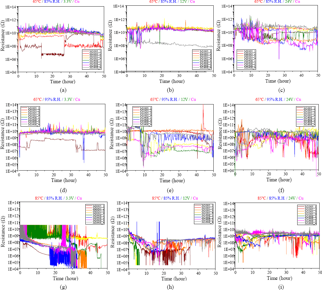
Fig. 5 illustrates the results of ECM tests conducted under three different temperature-humidity conditions and three applied voltage conditions, demonstrating the reduction in insulation resistance due to dendrite formation. The occurrence time of ECM was determined by calculating the points at which the insulation resistance fell below 10
6 Ōä” twice
3-6), and these results are presented in
Table 1.
Fig.┬Ā5
In-situ monitoring results of insulation resistance, (a-c) 65┬░C/85%R.H., (d-f) 65┬░C/95%R.H. and (g-i) 85┬░C/ 85%R.H. temperature-humidity conditions and (a,d,g) 3.3 V, (b,e,h) 12 V and (c,f,i) 24 V applied voltages
Table┬Ā1
ECM occurrence time with THB test conditions with three kinds of applied voltages and temperature-humidity conditions
|
Applied voltage (V) |
Samples |
65Ōäā/85%R.H. |
65Ōäā/95%R.H. |
85Ōäā/85%R.H. |
|
3.3 |
1 |
1306 |
98 |
33 |
|
2 |
500 |
38 |
17 |
|
3 |
223 |
75 |
19 |
|
4 |
239 |
52 |
29 |
|
12.0 |
1 |
1235 |
56 |
3 |
|
2 |
1235 |
50 |
No Failure |
|
3 |
1235 |
9 |
16 |
|
4 |
231 |
8 |
No Failure |
|
24.0 |
1 |
No Failure |
153 |
64 |
|
2 |
27 |
49 |
No Failure |
|
3 |
27 |
4 |
No Failure |
|
4 |
No Failure |
4 |
No Failure |
Under the applied voltage of 3.3 V, the ECM occurrence time at 65┬░C/85% R.H. was 1,306 hours, whereas it was fastest at 85┬░C/85% R.H., taking only 17 hours. At 24 V, the ECM occurrence time surprisingly measured 64 hours at 85┬░C/85% R.H., indicating a slower ECM occurrence compared to lower voltage conditions.
However, it was observed that under conditions with temperatures lower than 85┬░C, such as the 65┬░C/85% R.H. condition, the tendency for ECM to occur increased more rapidly as the voltage was raised. This trend was similarly observed under the 65┬░C/95% R.H. condition. However, it appears that beyond the condition of 85┬░C/85% R.H., the increase in the acceleration of ECM occurrence due to rising temperature tends to diminish. Therefore, for the assessment of ECM sensitivity, applying higher voltages at lower temperatures and higher humidity conditions seems to be a favorable approach to comparatively assess the acceleration of ECM occurrence.
3.2 Analysis of Dendrites on MLCC Electrodes
Fig. 6 displays optical microscope images of the top surface of MLCCs after THB tests lasting 2,934 hours under three different conditions: 65┬░C/85% R.H., 65┬░C /95% R.H., and 85┬░C/85% R.H. The initial time of occurrence when the resistance of MLCC components fell below 10
6 Ōä” twice or more was marked on each componentŌĆÖs image. Upon examination through a microscope, distinct dendrite formations were not observed. However, SEM and EDS analysis of the MLCC surface, as shown in
Fig. 7, revealed the migration of Cu and Sn elements. At lower temperature conditions, although distinct dendrites were not observed on the surface of the MLCC, it was evident that elements on the surface of the MLCC electrode were forming dendrites, growing from the (-) electrode towards the (+) electrode. This aligns well with prior studies suggesting that higher temperature and voltage conditions in THB tests generally increase the formation and growth rate of dendrites
3-15).
Fig.┬Ā6
Stereo-microscope images of MLCCs after 2,934 h THB tests with various temperature, humidity and applied voltage
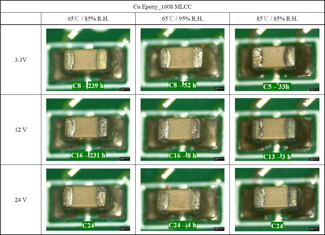
Fig.┬Ā7
SEM microscographs of (a,b) MLCCs top surface after 2,934 h THB test under 65┬░C/95%R.H. and (c) EDS analysis result
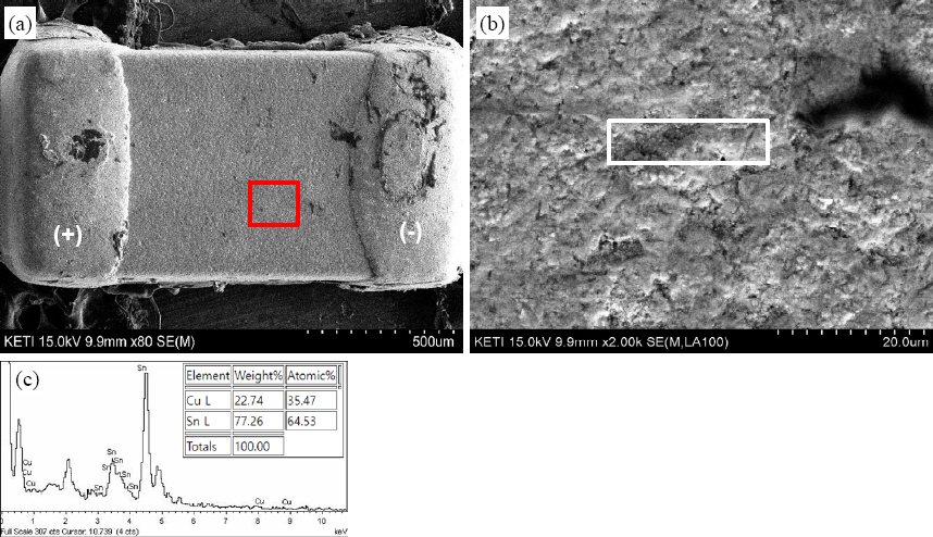
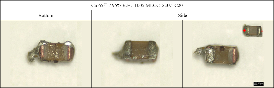
Fig. 8 shows optical microscope images of the bottom and side surfaces of the MLCC component after its removal post-THB test. Observations of the ceramic surface of the MLCC body, excluding the electrodes on the bottom soldered to the substrate, revealed dendrite formation, a phenomenon also observed on the side surfaces. This suggests that moisture tends to infiltrate and remain trapped in the space between the component and the substrate, leading to a higher incidence of ECM on the bottom surface of the MLCC compared to the top surface that is exposed more. Consequently, for MLCC components of the same capacity, it was noted that those sized 1608 tend to show lower ECM occurrence susceptibility than those sized 1005, due to the broader spacing between the (+) and (-) electrodes and the larger gap under the component when mounted on a PCB. These findings can be useful in determining the component size criteria during the design of circuit boards for electronic products. For MLCCs of smaller capacities, establishing a guideline for the minimum feasible component size at certain capacities could help reduce ECM susceptibility in MLCC components.
Fig.┬Ā8
Optical microscographs of MLCCs after 2,934 h THB test under 65┬░C/95%R.H
3.3 Weibull Distribution Analysis on ECM Occurrence
The results of the Weibull distribution analysis for the occurrence times of ECM are depicted in
Fig. 9, with Figs.
9(a-c) representing the cumulative failure times due to ECM under the conditions of 65┬░C/85%R.H., 65┬░C/95%R.H., and 85┬░C/85%R.H., respectively. Additionally, Figs.
9(d-f) display the graphs for cumulative failure times of ECM at varying test voltages of 3.3 V, 12 V, and 24 V, under each condition. At a constant temperature, an increase in humidity was observed to increase the susceptibility to ECM occurrence as the voltage increased. For MLCCs using Cu paste as the electrode material, the most rapid ECM occurrence time was noted at an applied voltage of 12 V under the condition of 85┬░C/85%R.H.; conversely, under 65┬░C/85%-R.H. conditions, ECM occurred sequentially with increasing applied voltages. Under conditions of very high humidity and temperature, the oxidation of electrode materials accelerates, resulting in the formation of a passivation film on the surface of the electrode materials. This phenomenon appears to reduce the electrochemical ionization rate of materials such as Sn and Cu used in MLCC electrodes, consequently delaying the ECM occurrence time
6). With a constant voltage applied, more severe temperature and humidity conditions resulted in a quicker onset of ECM occurrences. However, at an applied voltage of 24 V, differences in ECM occurrence times across the three humidity conditions were not significant, suggesting that the environmental differences in temperature and humidity are less impactful at higher voltages. Therefore, it can be inferred that at higher voltages, the likelihood of ECM occurrence is elevated even under lower temperature and humidity conditions.
Fig.┬Ā9
Weibull distribution analysis results after various THB test of 1608 MLCCs, (a) 65┬░C/85%R.H., (b) 65┬░C/ 95%R.H. and (c) 85┬░C/85% temperature-humidity conditions and (d) 3.3 V, (e) 12 V and (f) 24 V applied voltages

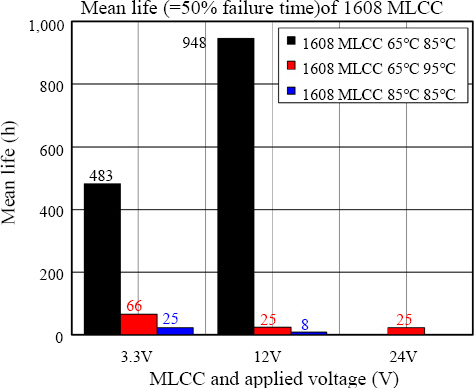
The Weibull distribution analysis curves derived from the three voltage conditions and three humidity conditions calculated the time at which 50% cumulative failures occurred as the mean life of ECM occurrence in MLCC components, as shown in
Fig. 10. An increase in applied voltage tended to decrease the ECM mean life. Notably, under the condition of 65┬░C/85%- R.H., the ECM lifespan at an applied voltage of 3.3 V was shorter than at 12 V. This phenomenon is ascribed to the formation and breakdown potential of the passivation film, resulting from the electrochemical ionization of elements such as Cu and Sn in the Cu epoxy-coated electrodes
6). More detailed research on the impact of the formation and breakdown of passivation films on ECM occurrence is ongoing. Nevertheless, it was observed that ECM occurrence times decrease with an increase in temperature under the same humidity conditions, and similarly, ECM occurrence times shorten with increasing humidity at the same temperature. From these results, it is deduced that an effective strategy to suppress ECM occurrence in small passive components used in electronic devices would involve lowering the PCB substrate temperature and enhancing the internal environmental conditions of the electronic device casing to prevent moisture absorption.
Fig.┬Ā10
Mean life time comparison of applied voltage under various temperature and humidity test conditions
4. Conclusion
This study evaluated the ECM susceptibility of 1608 MLCC components used in automotive electronics, conducting THB tests at applied voltages of 3.3, 12, and 24 V, under conditions of 65┬░C/85%R.H., 65┬░C/ 95%R.H., and 85┬░C/85%R.H. The findings can be summarized as follows:
1) Under THB test conditions at temperatures lower than 85┬░C, the occurrence time of ECM was found to be faster with increasing voltage. This trend was consistent at 65┬░C/95%R.H., however, starting from the condition of 85┬░C/85%R.H., the trend of accelerated ECM occurrence due to increasing temperature appeared to diminish. Therefore, for ECM evaluation, applying higher voltages in a lower temperature but higher humidity environment, like 65┬░C/95%R.H., seems to be a conducive condition for accelerating the occurrence of ECM in MLCC components.
2) The observation with an optical microscope revealed that the occurrence of ECM on MLCC component surfaces was not confined to just the top surface of mounted MLCCs, but also on their bottoms and sides. The presence of relatively more moisture locally between the MLCC component and the PCB substrate, compared to the MLCC top surface, is attributed to rapid ECM occurrence at the bottom. Thus, using 1608- sized MLCC components instead of 1005-sized ones, under the same capacitance, can more effectively reduce ECM susceptibility. Based on these results, determining a guide for component size relative to MLCC capacitance can help in reducing ECM susceptibility in MLCC components.
3) Under the same applied voltage conditions, more severe temperature and humidity conditions demonstrated rapid ECM occurrence times, and higher applied voltages showed less sensitivity to temperature and humidity environments. Therefore, it was observed that with higher applied voltages, the likelihood of ECM occurrence remained high even under conditions of low temperature and humidity. Moreover, within the same humidity, ECM occurrence times shortened as the temperature increased, and conversely, with the same temperature, an increase in humidity also reduced ECM occurrence times. These results suggest that improving the internal environmental conditions of electronic component cases can be effective in suppressing ECM.
Acknowledgments
This study was conducted with the support of research funding from Hyundai Mobis, and the authors extend their gratitude for this assistance.
References
2. D. B. Lee, J. H. Kim, S. K. Kang, S. W. Chang, J. H. Lim, and D. S. Ryu, Acceleration Test of Ion Migration for PCB Electronic Reliability Evaluation, J. of Power. Syst. Eng. 9(1) (2005) 64ŌĆō69.
5. W. S. Hong, S. B. Jung, and K. B. Kim, Analysis Method of Metallic ion Migration, J. Weld. Join. 23(2) (2005) 32ŌĆō40.
7. H. M. Lee, M. S. Kim, and W. S. Hong, Solder Joint Degradation and Electrochemical Metallic Ion Migration Property of Solder Joints with Surface Finish,
J. Weld. Join. 41(4) (2023) 265ŌĆō274.
https://doi.org/10.5781/JWJ.2023.41.4.5
[CROSSREF] 8. S. Zhan, M. H. Azarian, and M. Pecht, Reliability of Printed Circuit Boards Processed Using No-Clean Flux Technology in Temperature-Humidity-Bias Conditions,
IEEE Trans. Device. Mater. 8(2) (2008) 426434.
https://doi.org/10.1109/TDMR.2008.922908
[CROSSREF] 10. S. O. Ha and S. B. Jung, Drop Reliability Evaluation of Sn-3.0Ag-0.5Cu Solder Joint with OSP and ENIG Surface Finishes, J. Microelectron. Packag. 16(1) (2009) 33ŌĆō38.
12. S. H. Kim, J. M. Kim, S. H. Yoo, and Y. B. Park, Effects of PCB Surface Finishes on Mechanical Reliability of Sn-1.2Ag-0.7Cu-0.4In Pb-free Solder Joint,
J. Microelectron. Packag. 19(4) (2012) 57ŌĆō64.
https://doi.org/10.6117/kmeps.2012.19A057
[CROSSREF] 13. ISO 9455-17, Soft Soldering Fluxes - Test methods - Part 17;Surface Insulation Resistance Comb Test and Electrochemical migration Test of Flux Residues.
International Standardization Organization (ISO). (2022),
https://www.iso.org/standard/32830.html
14. I. H. Jang, J. H. Kim, G. G. Oh, Y. J. Lee, H. W. Lim, and Y. O. Choi, Main Factors that Effect on the Ion-Migration of PCB, J. App. Reliabi. 16(3) (2016) 202ŌĆō207.
15. J. Yu, S. Kim, W. S. Hong, and N. Kang, Intermetallic Compound Growth Induced by Electromigration in Sn-2.5Ag Solder Joints with ENEPIG Surface Finish,
J. Weld. Join. 40(3) (2022) 225ŌĆō232.
https://doi.org/10.5781/JWJ.2022.40.3.3
[CROSSREF]


 PDF Links
 PubReader
 ePub Link
 Full text via DOI
 Download Citation
 Print
Print


