


1. Introduction
2. Materials
3. Experiment
4. Result and Discussion
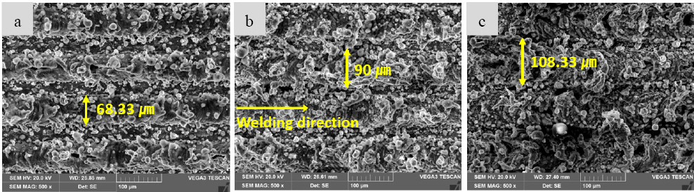
4.1 Weld surface appearance


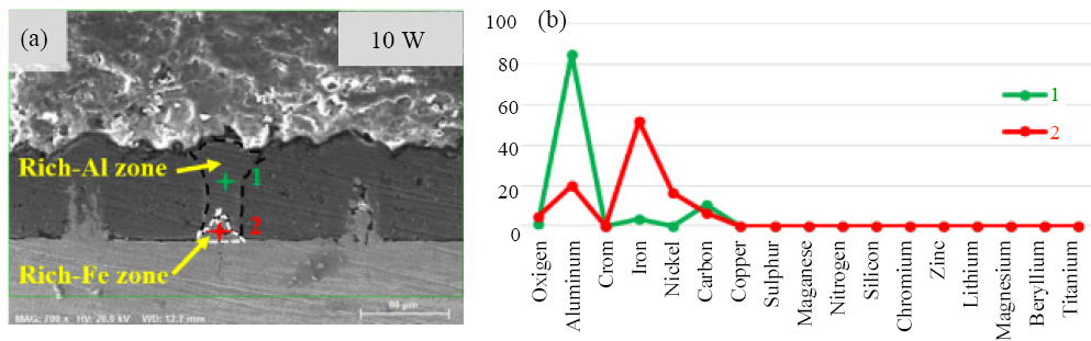
4.2 EDX analysis
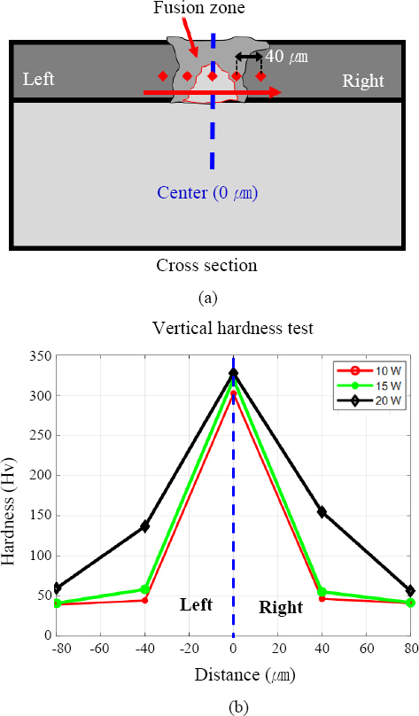
4.3 Hardness test
5. Conclusion
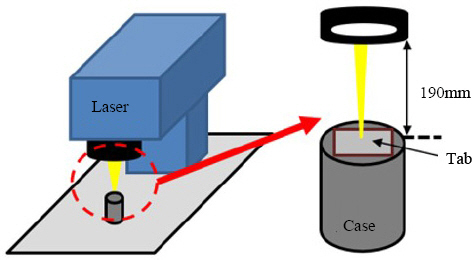
1) It is possible to weld the different thicknesses and materials of the battery case and tab with the nanosecond pulsed fiber laser.
2) The laser power has a significant impact on the formation of weld metal and spatters on the weld surface. When higher laser power is used, more molten materials are produced and cover the surface voids.
3) The fusion zone through the analysis of a cross-section of the joints revealed two separate intermixture solidified materials, including Al-rich and Fe-rich zone. As a result, a rapid increase of the hardness at the center of the fusion zone is reported.
4) Fusion zone, especially the Fe-rich zone is obtained with the highest hardness and the hardness increases with increasing laser powers.
5) Future studies would focus on the dislocation of voids formation depends on laser powers. Moreover, intermetallic compounds and the intensive fusion zone analysis will be taken into account.
 PDF Links
 PubReader
 ePub Link
 Full text via DOI
 Download Citation
 Print
Print


