


1. Introduction
Tailor welded blanks (TWB) are an assembly of sheet metals manufactured by joining similar or dissimilar materials of same or different thickness1-3). The TWB offers a reduction in the overall weight of the structure. TWBs cut the manufacturing cost of the components panel through an optimal distribution of material in an assembly, such as employing stronger materials at highly stressed region while thinner sheets at the lower stress section4). As a result, the properties of the blank is tailored to meet the requirement of componentŌĆÖs structural integrity, strength and stiffness4). The use of aluminium TWBs has gained popularity in the automotive sectors as aluminium offers a considerable weight reduction which in turn improves the fuel efficiency1,5). However, fusion welding of aluminium alloys of different thicknesses possesses several challenges such as porosity and hot cracking in the weld metal, severe distortion, and the development of refractory oxide layer on surface4-6). Further, the high reflectivity of aluminium makes the process unstable4-6). The Friction stir welding (FSW) is a solid-state welding process that can be used as a recourse to overcome the difficulties in fusion welding of aluminium alloys4).
The reported studies on tailored welding of similar or dissimilar aluminium alloys of different thickness by FSW process are limited in the literature1-10). Tavares et al. (2013) reported that the FSW improved the mechanical properties of the TWB made by different thicknesses of AA2198 to achieve the lighter structures7). Zadpoor et al. (2008, 2010) found that the joint strength in friction stir welded blanks of AA2024 and AA7075 decreased with increase in plate thickness from 1.2 to 2.5 mm2,3). Sheikhi et al. (2007) studied the effect of process parameters and tool geometry on mechanical properties of friction stir welded tailor blanks of AA6181 with thickness combination of 1 to 2 mm4). The authors obtained satisfactory surface finish with a maximum joint strength of around 91 to 99% of the base metal strength. In another study, Bonoome et al. (2007) achieved sound and defect free joint in friction stir butt welding of AA5754 and AA6181 with different thicknesses of 1 and 1.5 mm1). Fartini et al. (2007) investigated the influence of tool tilting angle on the mechanical strength of AA7075 TWB with thicknesses of 1 and 2 mm and found the maximum joint strength of 80% of the parent metal ultimate tensile strength8). Sahu et al. (2017) found maximum joint strength around 99% of the base metal using tilted machine bed in joining AA1050 alloy by FSW with workpiece thickness ratios of 1.33, 1.67 and 29). In another study, Nadikudi et al. (2015) investigated the formability of TWB of AA6061 and AA2014 made by FSW using five different tool pin profiles10). The authors found the blank prepared by a square pin provided better formability in comparison to the other tool pin profiles. The reported experimental studies provide an insight of FSW of different thickness aluminium alloys. However, the effect of workpiece tilting angle in joining of varying thicknesses aluminium alloys by FSW process is few in the literature.
The present work reports the feasibility to join different thicknesses AA5052-H32 in butt configuration using FSW process by tilting the bottom surface of the workpiece. Further, an attempt is undertaken to study the influence of varying workpiece tilting angle and process parameters on mechanical properties of the weld.
2. Experimental Details
The AA5052-H32 of thicknesses 1.5 and 2.5 mm was selected as a base material. Table 1 shows the chemical composition and mechanical properties of the base material. A typical gantry type FSW machine was employed to join the base materials in butt configuration using WC-12% Co made cylindrical tool. Table 2 shows the tool dimensions. The angle between the machine bed and bottom surface of plates (the rotation angle of the workpiece) was varied from 0 and 1┬░. The thinner plate was placed on advancing side and thicker plate on the retreating side. Fig. 1 shows the schematic diagram of the detailed experimental setup. The tool was set at a tilt angle of 2┬░ with the vertical axis in the direction of welding. Table 3 depicts the welding conditions that are used for the experiments. The welding conditions were selected based on several trial experiments after achieving a continuous bead profile without crack under visual inspection. The cross-section of the bead was measured after polishing and etching with KellerŌĆÖs reagent. A universal testing machine (Shimadzu: EHF-EF200kN, Hydraulic type) was employed to evaluate of the joint strength of the specimen at a crosshead speed of 1 mm/min as per ISO 6892-1:2016 standard. The Vickers micro-hardness was measured along the joint cross-section at the mid-thickness of the thinner plate. The Erichsen cupping test (Smtest in Korea: SMB-006-30T) was carried out based on ASTM 643-09 standard to evaluate the formability of joints using 10 mm punch tip at a speed of 20 mm/min.
Table┬Ā1
Chemical compositions of the base material
| Material | Si (%) | Fe (%) | Cu (%) | Mn (%) | Mg (%) | Ti (%) | Cr (%) | Al (%) |
|---|---|---|---|---|---|---|---|---|
| AA5052-H32 | 0.08 | 0.21 | 0.019 | 0.01 | 2.34 | 0.01 | 0.1 | Bal. |
Table┬Ā2
Mechanical properties of the base material
| Material | Yield strength (MPa) | Tensile strength (MPa) | Elongation (%) |
|---|---|---|---|
| AA5052-H32 | 188 | 225 | 12 |

3. Results and Discussion
3.1 Bead Profile
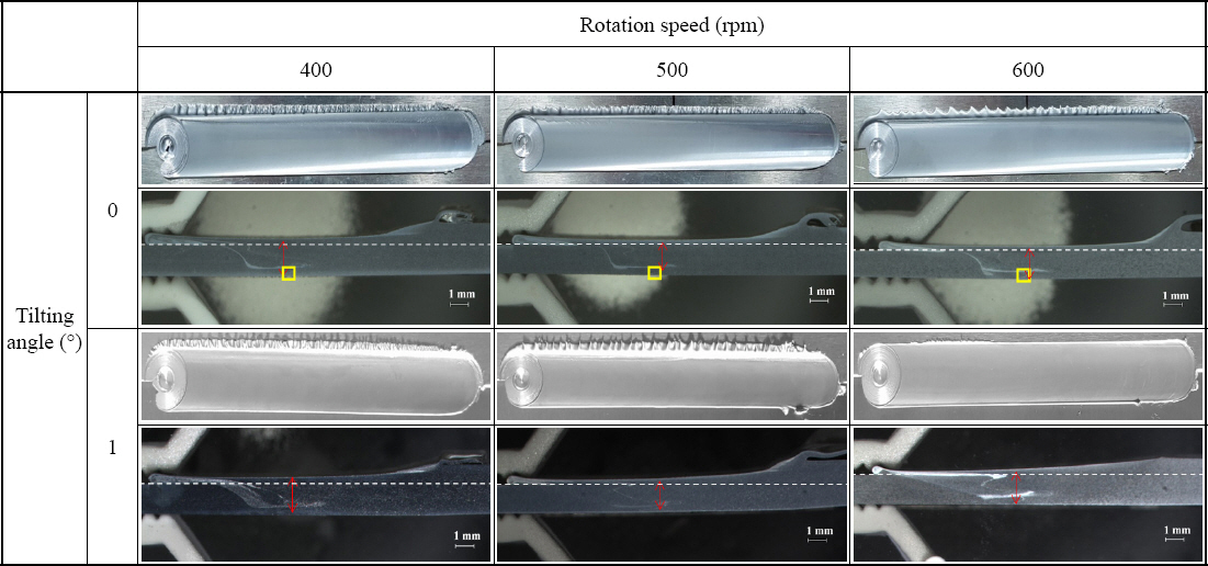
Fig. 2 shows the weld bead profiles and corresponding cross-sectional macrograph in joining of 1.5 to 2.5 mm thick AA5052-H32 at a rotational speed of 400 to 600 rpm for different combinations of workpiece tilting angle. Continuous beads were formed for all welding conditions. Fig. 2 illustrates the volume of burr in the retreating side for all welding condition. An increase in tilt angle leads to reduce difference of thickness between two materials. Therefore, plunge depth of FSW tool pin into the workpiece is increase, which lead to increase the flow of material. The yellow boxes in Fig. 2 show no bonding between the workpiece at the bottom side of the workpiece. That can be attributed to the insufficient plastic flow due to frictional heat and in sufficient pressing force due to the small contact area of the tool shoulder with the material surface. Fig. 2 shows the presence of joint line in the weld zone (white line), which is scattered oxide particles originated from the aluminium surface. Several authors reported that presence of joint line technical term had no detrimental effect on joint mechanical strength11,12).
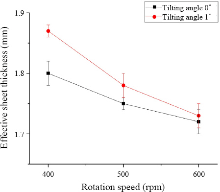
3.2 Effective Sheet Thickness
The minimum bonding distance from top surface of the plate along thickness direction is called the effective sheet thickness. The effective sheet thicknesses (red line) were measured from cross-sectional bead profiles in Fig. 2. Fig. 3 shows the measured effective sheet thickness at different workpiece tilting angles for three tool rotational speeds of 400 to 600 rpm. The effective sheet thicknesses increased with increasing tilting angle at any rotational speeds of 400 to 600 rpm. As the tilting angle increases, the plastic flow becomes more acltive, the effective sheet thickness increases because the base material is sufficiently softened due to the increased heat input and the plastic flow of the material is more easily caused by the increase of the agitating force. It is considered that the effective sheet thickness should be controlled by controlling the bonding type and the bonding condition so that the thickness of the effective sheet thickness can be secured.
3.3 Tensile Strength
This study investigated the butt - welding friction stir welding of aluminium alloy AA5052-H32. The tensile test was carried out in a direction perpendicular to the weld line, and three specimens were prepared for each condition. Fig. 4 shows the results of the tensile test for differnt rotational speed and tilting angle. The tensile strength was expressed as the average value of the three test samples.
Fig.┬Ā4
Tensile strength at different workpiece tilting angles for tool rotational speeds of 400, 500, 600 rpm

The lowest tensile strength of (193.7 MPa) (86% compared to the base material) was observed for a rotational speed of 600 rpm and a tilting angle 0┬░. That can be attributed to reduction of effective sheet thickness of the welded part during welding.
Tensile test results showed that rotation speed of 400 rpm, the maximum tensile strength of 212.6 MPa was obtained for tilting angle of 1┬░, and fracture occurred in the base material (BM) of 1.5t plate. Fig. 5 shows Facture tensile specimen at a rotational speed of 400 rpm and workpiece tilting angle of 1┬░. It could be noted that the strength was 95% of the ultimate tensile strength of AA5052-H32. The tensile strength at a rotational speed of 600 rpm showed lower strength as compared to that of 400 rpm. This is because the thickness of the welded part is decreased due to the thinning effect at heat input. The rotation speed of 400 rpm is considered to be a better condition as it shows a relatively high tensile strength than that of 600 rpm.

3.4 Hardness Distribution
Fig. 6 shows the hardness of the specimens with the highest tensile strength at a rotational speed of 400 rpm. The hardness was measured in the advancing side and retreating side at a position of the middle line and 0.5 mm away from the center. Hardness distribution of the test specimen showed that the hardness value tended to derease from the base material to the welds. The average hardness values were AA5052-H32 alloy were 69.4 Hv for 2.5 mm and 68.4 Hv for 1.5 mm, respectively. The hardness distribution value in the heat affected zone (HAZ) was about 54 Hv and the thermo-mechanical affected zone (TMAZ) was about 50 Hv in 1.5 mm of thin plate. The hardness distribution values of the HAZ and TMAZ in 2.5 mm thickness plate were measured as 61 Hv and 56 Hv, respectively. The maximum hardness value in the stir zone (SZ) was 63 Hv. Regardless of the plate thickness, hardness of the HAZ tended to be decreased sharply compared to that of the base material. The hardness of the SZ was lower than that of the base material. In addition, the hardness values ŌĆŗŌĆŗof the welds tended to be lower than those of the base materials under all conditions. The maximum hardness value of the welds was 60 Hv for rotational speed of 400 rpm with tilting angle of 1┬░. The average hardness of SZ was measured as 59 Hv. The measured hardness of HAZ, TMAZ were lower than that of the base material.
Fig.┬Ā6
Distribution of micro-hardness along the weld transverse section for FSW of AA5052-H32 alloy at a constant workpiece rotational speeds of 400 for different tilting angle of (a) 0┬░ (b) 1┬░
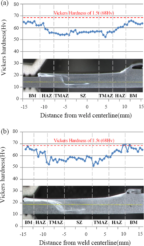
This is because an increase in dynamic recrystallization leads to reduce hardness value, and decrease in dislocation density in HAZ and TMAZ increase dynamic recrystallization17).
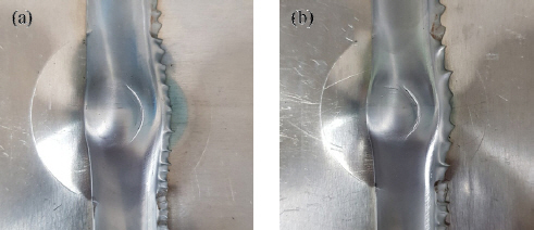
3.5 Erichsen Cupping Test
Fig. 7 shows the erichsen cupping test of the specimens with the highest tensile strength at a rotational speed of 400 rpm. Fracture load and displacement of erichsen test sample produced at 400 rpm and tilting angle of 0┬░ were 12.7 kN and 11.0 mm, respectively. Likely, fracture load and displacement of erichsen test sample produced at 400 rpm and 1┬░ were 13.6 kN and 12.6 mm, respectively. The fracture load and displacement on erichsen test sample of 1┬░ was higher than that of test sample of 0┬░. The hardness distribution of the TMAZ showed lower value than that of the other parts due to softening effect. Moreover, cracks were formed in TMAZ as a result of Erichsen cupping test. This result shows the good agreement with hardness distribution.
4. Conclusions
The following conclusions are derived from the present work:
1) No bonding is observed at the bottom side at tilting angle of 0┬░. It is believed that this is caused by insufficient plastic flow due to difference of thickness between two materials.
2) In the case of tilting angle 1┬░, the pin is inserted at the interface of the welded part to ensure smooth plastic flow.
3) The effective sheet thickness at tilting angle of 1┬░ was thicker than that of tilting angle at 0┬░. The maximum thickness was 1.66 mm at tilting angle of 1┬░ with rotational speed of 400 rpm.
4) The maximum joint strength is found to be around 212.6 MPa corresponding to rotational speed of 400 rpm and workpiece tilting of 1┬░.
5) The maximum hardness value at tilting angle of 1┬░ with rotational speed of 400 rpm were 60 Hv, which were 88% of the base material hardness. This is because the dislocation density decreases and dynamc recrystallization increases.
 PDF Links
 PubReader
 ePub Link
 Full text via DOI
 Download Citation
 Print
Print


