알루미늄 대상 보빈-마찰교반 용접용 툴 디자인에 관한 리뷰
A Review on the Design Rule for the Friction Stir Welding using Bobbin Tool for Aluminum
Article information

Abstract
Friction stir welding using a bobbin tool (BT-FSW) is a kind of friction stir welding (C-FSW) process in which a lower shoulder is added to the general friction stir welding tool. It is known as the useful method to reduce the Z-ax- is load required during the tool insertion and traveling for FSW. In addition, it can eliminate the backing plate, and actively respond to part deformation. For this reason, research on the application of BT-FSW is expanding from low melting temperature materials such as aluminum and magnesium to high melting temperature materials. However, no relevant studies on BT-FSW can be found in Korea. This study aimed to present tool design guidelines specifically for BT-FSW. Summarized information on variables to be considered when designing the BT-FSW tool has been described, such as pin and shoulder diameter, shoulder gap, pin and shoulder feature. The design of the tool is a significant step in set-up the BT-FSW process, and should be considered according to the material characteristics (viscosity, plasticity…) and thickness. The pin diameter that is similar to the thickness of material, and the shoulder diameter that is 2 to 3 times wider than the pin diameter were recommended. The shoulder gap, the distance between the upper and lower shoulder, is generally machined to match the material’s thickness or fabricated to be shallower than. Since the pin shape directly affects the vertical and horizontal direction movement into the stir zone, the pins with 3 to 4 flat faces or threaded are more practical than the cylindrical pin shape.
1. 서 론
보빈 툴을 이용한 마찰교반용접(Bobbin tool friction stir welding, BT-FSW)은 기존의 마찰교반용접(Con- ventional friction stir welding, C-FSW)의 변형공 정으로, 기존의 마찰교반용접의 툴에 하단 숄더를 추가 한 툴을 사용한다. BT-FSW를 적용하는 경우 툴의 삽 입 및 회전에 의해 발생하는 Z축 하중을 저감할 수 있 으며, 백킹 플레이트가 필요없고 용접부의 위치에 능동 적으로 대응할 수 있다1). 또한 C-FSW에 비하여 접합 부의 고른 온도분포가 형성되고 용접부의 두께방향으로 결정립 크기가 고르게 분포한다고 알려져 있다2). 다만, BT-FSW는 시작부와 종결부의 열린 경계에서만 사용 이 가능하며, 하부 숄더의 설계가 요구되어진다.
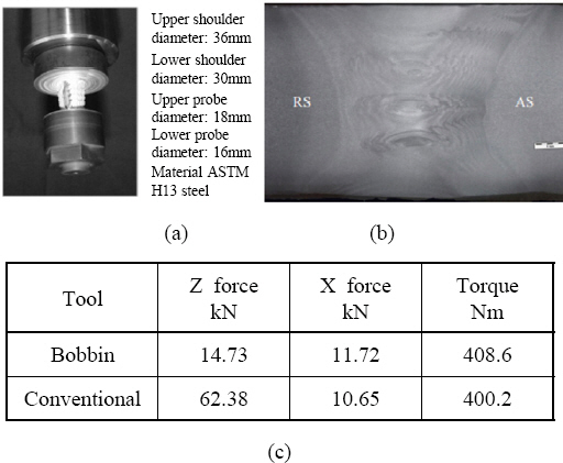
Fig. 1은 실제로 BT-FSW공정을 이용하여 25 mm 두께의 AA6082-T6합금을 용접한 사례를 나타낸다1). Fig. 1(c)는 X축, Y축, Z축에서 측정된 최대 하중을 나타내었으며, C-FSW에 비해 BT-FSW를 적용한 경 우 Z축 하중이 크게 감소한 것을 확인할 수 있다. C- FSW의 경우 툴과 소재사이의 반발력으로 인해 높은 Z축 하중이 요구되지만, BT-FSW의 경우는 구조적인 특징으로 인해 용접방향으로 이동하기 위한 하중만이 요구된다. 공정의 특징상 소재에 완전한 침투가 전제되 므로, 결과적으로 BT-FSW를 사용한 경우 적은 부하 로도 안정적인 용접부를 확보할 수 있음을 알 수 있다.
보빈 툴을 활용하면 소재의 두께 및 높이의 변화에 능동적 대응이 가능하다. Self-support FSW, Self- aligning and adjusting FSW, Pinless bobbin tool FSW, Semi-stationary shoulder FSW(SS-FSW), Dual-rotation BT-FSW과 같은3-6) 다양한 종류의 BT- FSW 툴의 형상이 Fig. 2와 같이 제안되고 있다. The Welding Institute(英, TWI)는 Pinless BT-FSW의 특허를 등록하였으며 (Fig. 2(b))7), 이 디자인 툴을 활 용하여 3mm 두께의 AA6082-T6 합금을 성공적으로 접합하고 적은 잔여물과 두께변화의 대응성의 장점을 증명하였다. BT-FSW는 상단과 하단, 두개의 숄더가 존재하기 때문에, 숄더의 움직임을 각각 제어하는 시도 도 연구된 바 있다3).

Examples of various bobbin tools
Goebel의 연구진3)은 Semi-stationary shoulder BT-FSW 공정을 제시하였다 (Fig. 2(a)). 상단의 숄 더가 회전하지 않는 조건과 기존의 BT-FSW 공정을 비교하였을 때, 상단의 숄더가 돌지 않는 Semi-sta- tionary Shoulder BT-FSW에서 현저하게 적은 버와 결함을 가진 접합이 형성됨을 확인하였다. Wang의 연 구진6)은 더욱 나아가 상단과 하단의 회전을 반대로 설 정하는 Dual rotational BT-FSW 공정을 이용하여 AA2198-T851 접합을 시도하였다. Fig. 2(b)에서 보 이는 Dual rotational BT-FSW는 상단 숄더와 하단 숄더의 회전방향의 차이로 불균형한 유동을 생성하여 효 과적인 재료의 흐름을 야기함으로써 기존의 BT-FSW에 비해 효과적으로 보이드 결함을 줄이는 것을 확인하였다.
국외에서는 경량소재인 알루미늄, 마그네슘에서 철강 소재까지 BT-FSW의 적용 연구가 확대되고 있으나, 국내에는 관련 연구가 전무한 상태이다. 본 리뷰에서는 BT-FSW공정 설계의 첫 단계인 툴의 설계에 대한 가 이드라인을 제시하고자 하였다. 공정 중 발생되는 마찰 열 및 소성유동은 툴-부재와의 접촉 및 마찰과 직접적 관계를 가지기 때문에 툴의 설계는 매우 중요하다. 툴 은 크게 핀과 숄더로 구성되어 있으며, 핀과 숄더에 대한 직경, 형상특징요소에 대한 설계를 필요로 한다. BT- FSW에서는 C-FSW공정과 달리 하단의 숄더가 추가 됨에 따라 상단과 하단 두 숄더의 거리에 대한 변수인 숄더갭 변수가 추가된다. 본 리뷰에서는 핀과 숄더의 직경, 숄더갭, 핀의 형상특징, 숄더의 형상특징의 순서 로 간략히 BT-FSW공정의 툴 설계를 요약하여, 보빈 툴 설계를 고려시 필요한 정보를 제공하는 것을 목표로 하였다.
2. 보빈툴의 설계
툴의 설계는 마찰에 의한 입열과 소재의 소성유동에 영향을 주며, 최종적으로는 용접부의 품질을 결정한다. 핀은 입열과 소성유동에 영향을 미치며, 숄더는 입열과 버(burr)의 발생에 영향을 미치는 것이 일반적이다8,9). 마찰에 의한 입열과 소재의 소성유동은 비례관계이며, 상호유동적이다. 적은 입열은 충분한 소성유동을 일으 키지 못하여 Fig. 3에서 보이는 커팅결함을 일으키며, 과한 입열은 과유동을 유발하여 많은 버와 터널, 보이 드결함을 야기한다. 때문에 BT-FSW 공정을 수행함에 있어 입열과 유동과의 관계를 고려한 툴의 설계 및 공 정 설계가 요구되어 진다.

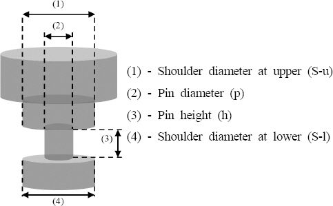
Table 1에 참고문헌에서 사용된 소재의 두께, 상하 숄더의 직경, 상하 숄더사이 간극(숄더갭)을 나타내었 다. 표에 나타낸 (S-u/t)는 상부 숄더와 부재 두께와 의 비율, (S-l/t) 하부 숄더와 부재 두께와의 비율, (h/t)는 핀의 높이와 부재 두께와의 비율, 그리고 (p/t) 는 핀의 직경과 부재 두께와의 관계를 의미한다.

Summarized design features of shoulder and pin
2.1 핀, 숄더의 직경 설계
툴의 설계에 있어 가장 선행되어야 할 요소는 핀과 숄더의 직경으로 소재의 종류와 두께에 따라 설계가 이 루어진다. SS-FSW와 같이 핀과 숄더의 특징요소가 변 경되는 경우 추가적인 설계변경이 요구되어지기도 한다.
Fuse의 연구진11)은 6 mm 두께의 Al6061-T6를 마찰교반 용접하는데 있어, 상하부 숄더가 24 mm으로 가공된 툴을 활용하였다. 이외에도 많은 참고문헌에서 부재 두께의 약 3배, 핀직경의 2 ~ 2.5 배에 해당하 는 숄더 직경 설계를 다수 확인할 수 있었다 (Fig. 4).

Summarization of geometrical feature ratio used in previous literature
BT-FSW는 완전용입이 전제된 공정이므로, 핀의 직 경은 용접부의 크기를 결정하는 직접적 요인이며, 소재 강도와 두께를 동시에 고려하여 핀의 직경을 선정 후 공정을 진행할 필요가 있다. 이는 핀의 직경이 너무 작 은 경우 공정 중 발생하는 부하에 의해 툴의 파손 및 변형이 발생할 가능성이 높기 때문이다. 부재의 두께가 두꺼워질수록 장비 및 툴에 걸리는 부하가 증가하기 때 문에 소재의 두께와 유사하게 핀 직경을 설계하지만, 부재의 두께가 얇은 경우에는 1.5 ~ 2배의 핀 직경을 활용한 사례도 보고되었다(Table 1)12).
2.2 숄더갭 설계
BT-FSW공정은 상단과 하단에 두개의 숄더가 존재 하기 때문에 두 숄더사이의 간극, 숄더 갭이 존재한다. 숄더는 소재의 유동방향을 제어하며 소재와의 마찰로 열을 발생시키는 역할을 수행한다. 공정 중 양단의 숄 더는 소재와 접촉한다는 가정이 선행되기 때문에 소재 의 두께보다 큰 숄더갭은 합리적이지 못하다. 많은 연 구에서 소재 두께의 90 %~100 %에 달하는 작은 숄 더갭으로 툴을 설계한다12).
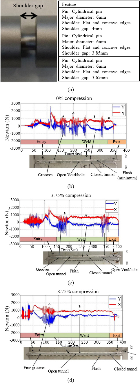
Sued12)는 숄더갭이 BT-FSW공정에 미치는 영향을 실 험적으로 확인하기 위하여 4mm AA6082-T6소재를 대 상으로 4mm(0%압축), 3.85mm(3.75%압축), 3.65mm (8.75%압축)의 숄더갭을 보유하는 툴을 설계하여 공 정을 수행하였다. Fig. 5를 통해 공정시간에 따른 X 축, Y축 하중 변화를 확인할 수 있다. 숄더갭이 작아질 수록 (압축이 커질수록) X축, Y축 하중 추세선의 흔들 림이 적어, 공정이 안정적임을 유추할 수 있다. 그러나 숄 더갭이 작아질수록 많은 버가 발생하였다. 특히 3.65mm 의 숄더갭의 경우(Fig. 5), 진행 방향에 걸리는 부하 로 인해 용접속도의 확보가 어려웠음을 예상할 수 있 다. BT-FSW공정의 숄더갭 변수는 아직 다양한 선행 연구가 이루어지지 않은 상황이며, 보다 체계화된 연구 가 요구된다1,10).
2.3 숄더 및 핀의 형상 설계
BT-FSW에서 숄더 및 툴의 형상특징에 대한 영향 분석은 제작의 높은 난이도, 형상 패턴의 마모 등 여러 문제로 인해 거의 존재하지 않는다. 그러나 C-FSW공 정에는 Fig. 6과 같이 숄더 표면에 패턴을 적용하여 소재와의 마찰열 극대화하는 연구2) 및 핀에 형상 특징 요소를 추가하는 연구가 진행된 바 있다31).
핀에 형성되어 있는 나사산은 추가 열을 발생시키며 나사산 방향과 같은 방향의 수직 유동에 영향을 미친다 인한 결함을 야기시킬 수 있음이 확인되었다. 숄더의 패턴은 내부의 유동물을 가압하며 마찰열 발생에 영향 을 미치며, 충분한 마찰열의 확보는 교반부의 유동성을 증진시킨다. 특히, BT-FSW는 숄더가 상하부에 모두 존재하기 때문에 교반을 위한 열 입력을 보다 쉽게 야 기시킬 수 있으며, 공정 중 상하부 숄더에 의해 발생되는 유동장으로 인해 부재는 압축력을 받게된다. 즉, BT- FSW의 품질은 수직방향의 유동보다 수평방향의 유동 에 주된 영향을 받음을 의미한다.
기 수행 연구결과를 살펴보면 3~4개의 면을 가진 나사선이 존재하는 핀 형상이 높은 품질의 BT-FSW공 정을 위하여 필요하다고 언급되고 있다10,12,31). 하지만 형상특징이 적용된 핀은 제작이 어렵고, 가공비 소요가 8,31). Sued의 연구진31)은 Fig. 7과 같은 6개의 툴을 제작하고 이를 이용하여 BT-FSW공정을 진행하였다. 툴 의 형상은 용접부의 유동을 변화시켜 용접부를 비대칭 적으로 형성시키거나, 과도/과소 수직유동의 형성으로 크며, 툴의 수명을 단축시킨다. 때문에 툴 수명를 향상 시키기 위한 소재에 관한 연구 및 제작이 용이한 핀 설 계의 연구가 필요할 것으로 판단된다.

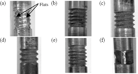
Pin figures of BT-FSW tools, (a) cylindrical thread- ed with 3 flats, (b) cylindrical threaded; (c) cylin- drical with grooves (1.5 mm), (d) cylindrical with grooves (2 mm), (e) cylindrical left hand and right hand
3. 결 언
본 리뷰에서는 BT-FSW를 수행함에 있어 툴의 설계 에 대한 간략한 가이드라인을 제공하고자 하였다. 용접 품질은 툴의 크기, 공정 변수, 용접 방향, 지그 장치와 이음부 관리 등과도 교호작용하기 때문에 툴이 용접 품 질의 모든 것을 결정한다고 할 수 없다. 그럼에도 불구 하고 BT-FSW 공정에서 툴은 소재와 직접적으로 마찰하는 부분으로, 내부의 소성유동 및 마찰열과 직접적인 관계가 존재한다. 때문에 툴의 설계가 조립품의 기계적 조직적 특성에 중대한 영향을 미친다고 할 수 있다.
문헌에서 확인된 BT-FSW의 핀의 직경은 소재의 두 께와 비슷하게 설정하는 것이 일반적이며, 숄더의 직경 은 핀직경의 2~3배로 설정하는 것이 추천되고 있었다. 숄더갭은 상부와 하부숄더의 사이거리로써, 소재 두께와 일치하게 설정하는 것이 일반적이나 소재두께의 0.9배 까지는 숄더갭이 줄어들수록 용접 안정성이 증가한다는 보고가 존재한다. 핀의 형상(다각, 골, 나사산…)이 없 는 경우보다는 3-4개의 플랫면 또는 나사선을 가진 핀 이 추천되며, 이는 핀의 형상이 교반부의 수직 또는 수 평방향 유동에 직접적인 영향을 미치기 때문으로 판단 된다. 반면, 숄더의 형상이 용접특성에 미치는 영향에 대한 보고는 거의 존재하지 않는다.
BT-FSW공정의 툴의 설계는 공정을 설정하는 첫 단 계이며 접합소재의 종류와 두께에 따라 신중히 설계되 어야 한다. 본 리뷰에서는 공정설계의 첫 단추라고 할 수 있는 툴의 설계에 대해 간략히 다루었다.
Acknowledgements
이 논문은 한국연구재단이 지원한 “스페이스파이오니어사업”으로 지원을 받아 수행된 연구결과입니다. [과제명: 공통격벽 추진제 탱크 제작을 위한 마찰교반용접 공정 개발 / 과제고유번호: 2021M1A3B9096763]