


1. Introduction
The environmental impact of internal combustion engine vehicles has heightened the transition to ecofriendly electric vehicles1,2). Consequently, domestic manufacturers predominantly opt for lithium-ion batteries in electric vehicles due to their relatively high energy density and ease of miniaturization and lightweight design3). Lithium-ion battery cells are primarily designed in cylindrical, prismatic, and pouch formats. Among these, the pouch cells, as depicted in Fig. 1, can minimize intercellular spacing, allowing for a higher energy density in the same volume compared to cylindrical and prismatic cells, thereby offering lightweight advantages.
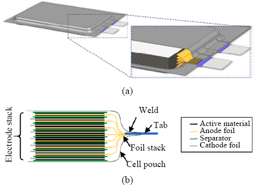
Pouch cells in lithium-ion batteries comprise a multi-layered structure consisting of a cathode, anode, and separator1), and aluminum (Al) and copper (Cu) are primarily used as electrodes2).
The electrodes of pouch cells are foils a few micrometers thick, and dozens of these electrode foils are connected to a lead tab via welding. The typical thickness of a lead tab ranges from 0.4-2.0 mm, and the more foils connected to a single tab, the lighter and more compact the battery4). However, welding these foils is challenging due to the high conductivity of the material, multiple layers of foil, and the close proximity of sensitive cell materials to the welding area5). Proper welding of multi-layered foils is crucial for battery performance and safety. In addition, welding defects can result in reduced electrical contact, thermal deformation, and decreased durability6).
Various welding techniques are employed for cell-level joining in secondary batteries, with laser welding and ultrasonic welding being the primary methods1,7). Ultrasonic welding is a type of solid-state welding and is characterized by minimizing heat input during the welding process. This protects the cell materials from thermal damage, shields the sensitive components inside, and reduces the impact of heat. Its solid-state nature also makes it advantageous for joining heterogeneous materials and multi-layered sheets8,9). On the other hand, laser welding, utilizing a high-density heat source, offers faster welding speeds, lower energy input per unit length, and precise energy control compared to conventional methods. Its non-contact nature ensures applicability to complex shapes, provided a clear optical path is maintained4).
Traditional arc welding, due to its high heat input, is unfavorable for heterogeneous metal welding and poses thermal risks to the chemical compounds inside battery cells3,8). Electric resistance welding has been used for cell welding for decades, but primarily for low-energy batteries rather than high-energy batteries. The high electrical and thermal conductivity of aluminum and copper used in lithium-ion batteries can reduce the process stability of resistance welding. Techniques to increase current density by reducing the total contact area through projection welding or by supplying very high welding currents (10-100 kA) within a short duration exist but are not ideal due to excessive heat and extensive deformation8,13).
A more recent method, wire bonding, is widely employed in the microelectronics industry and offers cost competitiveness and flexibility in interconnections. It involves the automatic feeding of silver, copper, or aluminum wires, each 0.01-0.05 mm thick, first joining to one substrate and then sequentially to others. However, wire bonding is generally suited for applications with low currents and voltages but is inadequate for the power transfer requirements of high-current, high-voltage lithium-ion batteries8,9). Mechanical joining is favored at the module level due to its ease of maintenance, repair, and disassembly, but at the cell level, it adds extra components and weight and may be prone to corrosion. Mechanical joining methods can also pose damage risks to the internal structure of the battery cells due to mechanical pressures or shocks associated with the joining process8-10). Friction stir welding, a solid-state welding method, is occasionally applied to battery cell joining. However, precisely controlling pressure is challenging, and the process can be further hindered by the presence of protective coatings or other materials on the cell surface. Recent advances have achieved high-quality battery welds using refill friction stir spot welding, but this approach can be constrained by access to the weld formation area and lengthy process times due to its complex procedure11,12).
As previously mentioned, ultrasonic and laser welding both have advantages over other welding techniques, and the strengths and weaknesses of these two processes are compared in Table 1. This review paper aims to delve into the mechanisms and features of ultrasonic and laser welding in multi-layer foil welding and to analyze the latest research and development trends both domestically and internationally.
Table┬Ā1
2. Review of Physical Requirements for Multilayer Foil Joints
2.1 Mechanical Properties
Lithium-ion battery structures must exhibit superior mechanical properties to prevent cell leakage, damage, or performance degradation6). According to the collision test requirements of ISO 6469-1, it is only stipulated that during a vehicle collision, battery pack components (such as battery modules and electrolytes) should not infiltrate the passenger compartment; however, detailed guidelines are lacking. Various approval standards for conducting stability tests on lithium-ion batteries differ depending on their application, and these can include extreme scenarios such as vehicle collisions or mechanical penetration of cells14). The minimum strength required for lithium-ion battery structures varies depending on the battery manufacturer, type of battery, and welding technology utilized. In the ultrasonic welding process, the design of battery cell joints is reconfigured based on the material combination, specifically the shapes of the horn and anvil. Consequently, comprehensive quality guidelines pertaining to this have not been fully established15). In the laser welding process, the strength of the cell joint varies depending on the length of the welding seam or the number of contact points, so a standard for measurement should be established first to enable quantification14). Currently, there is a scarcity of guidelines on the standard strength of battery cell joints, necessitating the development and implementation of standardized strength evaluation guidelines. Literature that provides joint strength values for multi-layer foil welding in the materials used in battery cells is summarized in Table 2.
Table┬Ā2
Summary of joint load for multi-layer foil assembly by laser and ultrasonic welding
| Process | Material (Top) | Material (Bottom) | Sonotrode size (mm) | Joint load (N) | Joint load (MPa) | Remarks | Ref |
|---|---|---|---|---|---|---|---|
| Ultrasonic | Cu-OF, 25 um*2 | Cu-OF, 100 um | 3├Ś3 | 3┬▒1 | 20 | T-Peel | 3) |
| C1220, 0.1 mm*3 | C1220, 0.2 mm | 20├Ś7 | 275 | 68 | T-Peel | 10) | |
| C1220, 0.2 mm | C1220, 0.1 mm*3 | 20├Ś7 | 400 | 100 | T-Peel | 10) | |
| C1220, 0.1 mm*3 | A1050, 0.2 mm | 20├Ś7 | 175 | 44 | T-Peel | 10) | |
| A1050, 0.2 mm | C1220, 0.1 mm*3 | 20├Ś7 | 150 | 38 | T-Peel | 10) | |
| Ni-coated C11000, 0.2 mm*3 | Ni-coated C11000, 1 mm | 9├Ś8 | 170┬▒10 | 31 | T-Peel | 21) | |
| Cu-OF, 8 um*40 | Ni-Coated Cu, 200 um | 9├Ś5 | 60 | 33 | T-Peel | 22) | |
| Ni-Coated Cu, 0.2 mm*3 | Ni-Coated Cu, 0.9 mm | 5.4├Ś5.4 | 700┬▒20 | 216 | Lap-Shear | 24) | |
| Ni (99.9%), 100 um | Cu (99.9%), 10 um*2 | 3├Ś3 | 10┬▒3 | 167 | U-tensile | 42) | |
| SM laser | Cu-OF, 0.3 mm | Cu-OF , 10 um*35 | - | 500 | 166.6 | Tensile Peel | 19) |
| MM laser + scanning | Cu-PHC, 8 um*40 | Cu-OF, 300 um | - | 490 | 81.6 | Lap-Shear | 5) |
| MM laser + scanning | Cu-PHC, 8 um*60 | Cu-OF, 300 um | - | 580 | 96.6 | Lap-Shear | 5) |
| MM laser + scanning | Cu-PHC, 10 um*50 | Cu-OF, 300 um | - | 350 | 58.3 | Lap-Shear | 5) |
| MM laser + scanning | Cu-PHC, 10 um* 40 | Cu-OF, 300 um | - | 514 | 85.6 | Lap-Shear | 1) |
| MM laser + scanning | AW-1050A, 15 um*40 | AW-1050A, 300 um | - | 92 | 15.3 | Lap-Shear | 14) |
| SM laser + scanning | AW-1050A, 15 um*40 | AW-1050A, 300 um | - | 242 | 40.3 | Lap-Shear | 41) |
2.2 Thermal and Electrical Properties
In lithium-ion battery cell joints, the maximum surface temperature of the cell and the contact resistance of the joint are crucial factors influencing battery stability, performance, and lifespan. Excessive temperature elevation in lithium-ion batteries and high contact resistance occurring within battery cells can lead to component damage, electrolyte decomposition, increased internal pressure, and even potentially result in fire or explosion hazards. Given that in pouch-type cell structures, the decomposition of electrochemically active materials starts at 80┬░C, 60┬░C is generally defined as the maximum temperature during manufacturing and processing11). When welding cells, it is essential to maintain a specific distance from the weld to the cell casing to ensure the temperature stays below a certain level, thereby preventing damage to the electrically active materials inside. Additionally, considering the prolonged exposure time at the welding site, it is vital to define the minimum time required to lower it below a certain temperature11). Internal resistance occurring at the interface between the electrode and the current collector of lithium-ion batteries should be less than 40 mŌä”, and factors such as surface roughness and oxide layer contamination can affect this resistance value16). If the contact resistance of laser welding and ultrasonic welding remains below 40 mŌä”, it is anticipated that significant resistive heating will not occur during the batteryŌĆÖs charging or discharging phases. Literature that presents the maximum surface temperature and electrical resistance values of multi-layer foil joint components, such as the tab-to-tab and foil-to-tab, used in battery cells is summarized in Table 3.
Table┬Ā3
Summary of welding peak temperature for multi-layer foil assembly by laser and ultrasonic welding
| Process | Material (Top) | Material (Bottom) | Maximum temperature (┬░C) | Electrical resistance (╬╝╬®) | Ref |
|---|---|---|---|---|---|
| Ultrasonic | C1220, 0.1 mm*3 | C1220, 0.2 mm | 90 | 58.1 | 10) |
| C1220, 0.2 mm | C1220, 0.1 mm*3 | 90 | 60.1 | 10) | |
| C1220, 0.1 mm*3 | A1050, 0.2 mm | 80 | 72.5 | 10) | |
| A1050, 0.2 mm | C1220, 0.1 mm*3 | 60 | 79.0 | 10) | |
| MM laser + scanning | Cu-PHC, 8 um*40 | Cu-OF, 300 um | 65 | - | 5) |
| MM laser + scanning | Cu-PHC, 8 um*60 | Cu-OF, 300 um | 70 | - | 5) |
| MM laser + scanning | Cu-PHC, 10 um*50 | Cu-OF, 300 um | 80 | - | 5) |
3. Ultrasonic Welding of Multilayer Foils
3.1 Ultrasonic Welding Mechanism
Ultrasonic welding occurs at temperatures below the melting point of the material, resulting in a minimal heat-affected zone. This method boasts excellent joinability, especially when dealing with heterogeneous materials, highly conductive materials, or very thin foil materials. Consequently, it is conducive for multilayer welding and heterogeneous material joining. Due to the minimal heat input in the welding zone, it is also predominantly used in cell joint applications3,15). An ultrasonic welding machine comprises a power supply unit that converts a 60 Hz current to a high-frequency current exceeding 20 kHz, a converter that transforms electrical energy into mechanical energy, a booster that amplifies the amplitude of mechanical vibrations originating from the converter, and a sonotrode horn which conveys the vibration to the stacked electrode and lead tab for welding17). The sonotrode horn and anvil are structured with tips possessing ridges, and these serrated patterns penetrate the parent material, inducing plastic deformation at the joint interface through high-frequency vibrations. The load on joints is determined by the plastic deformation and extrusion volume of the material at the welding interface18). Achieving consistent weld quality across various interfaces during ultrasonic welding of pouch-type cells is paramount in enhancing the performance of lithium-ion batteries19,20). However, mechanical damage risks exist for foils as thin as a few micrometers due to the hornŌĆÖs contact and lateral vibrations. The localized pressure from the sonotrode horn may induce varied bonding characteristics throughout the multilayer foil. While extensive research has been conducted on ultrasonic welding of two metal sheets, studies dealing with multilayer welding remain limited21).
3.2 Influence of the Horn and Anvil
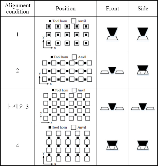
Shin et al.15,22) conducted ultrasonic welding on multilayer cell foils comprised of 40 layers of 8 um thick copper foil and a 0.2 mm nickel-plated copper sheet. They compared the power signal under conditions of 50 um amplitude and 4 bar pressure, based on the alignment and misalignment of the horn and anvil22). With the aligned horn, the welded area was relatively larger, resulting in an average output that was 100-200 W higher than that of the misaligned horn. By categorizing the alignment conditions of the horn and anvil into four levels (Fig. 2) and comparing the weld lobe regions, they found that alignment condition 1, where the horn and anvil were in direct contact, formed a broader optimal welding area15). Also, the average strength of the welding zone under alignment condition 1 exhibited the highest value.
Tsujino et al.23) developed a sonotrode horn equipped with a diagonal slit and capable of a 20 mm wide complex vibration to form smaller welding spots on battery cells and improve vibration characteristics. With this approach, they successfully welded 30 layers of 20 ┬Ąm thick copper foil with a nickel-plated copper sheet without deformation. Shawn et al.21) studied the impact of the roughness of the anvil on weld formation in multilayer ultrasonic welding. For that purpose, they used two types of anvils (with different knurl patterns: fine and coarse) to ultrasonically weld three 0.2 mm thick nickel-plated copper sheets and one 1.0 mm thick nickel-plated copper sheet, as depicted in Fig. 3. With the fine anvil, the vibrational amplitude of the four copper sheet layers converged at 60 ┬Ąm, while the coarse anvilŌĆÖs amplitude converged at 30 ┬Ąm. Moreover, the coarse anvil exhibited superior performance in terms of joint density and strength across multiple welding interfaces. This resulted in reduced relative movement between the four layers of copper sheets and the tool, extending tool life. However, the design of the horn and anvil shapes for battery cells varies depending on material combinations, and guidelines for welding quality have not yet been established15).
Fig.┬Ā3
Anvil geometry used in the experiment and Progress of vibration amplitude of horn and four metal layers during initial stages (0~0.1 sec) of welding process when using (a) fine anvil, and (b) coarse anvil21)

3.3 Configuration of Multi-layered Top and Bottom Plates
Shin et al.10) conducted ultrasonic welding experiments to understand the welding mechanism of the multi-layered joint area for electrode foils and tabs in lithium-ion battery cells. They alternated the positions of three 0.1 mm-thick copper sheets with a 0.2 mm- thick copper sheet during overlap welding. It was found that when the thinner sheets were stacked closer to the horn side, better joint strength was achieved at the welding interface. When the lead tabs of the top/bottom plates were changed to aluminum and ultrasonically welded with three copper electrode sheets, it was observed that materials with lower hardness values (i.e., aluminum) were more susceptible to vibration. The teeth of the horn and anvil protruded deeper into the sheet surface, causing easier plastic deformation.
Z.L Ni et al.24) inserted an Al 2219 alloy particle layer between a 0.5 mm thick copper sheet and a 1.0 mm thick aluminum sheet and welded them using ultrasonic welding after changing the top/bottom plate materials. They discovered that when aluminum was positioned on the horn side, the joint shear strength was 27.3 MPa higher. This was attributed to aluminum having a lower thermal conductivity than copper, causing the Al 2219 alloy particles to press deeper into the aluminum sheet and undergo more plastic deformation.
3.4 Effect of Pre-heating
Luo et al.25) proposed that in multilayer ultrasonic welding, pre-heating softens the material, enabling the sonotrode horn to compress and vibrate multiple sheet layers more effectively, thereby enhancing the stability of the welding process. They layered three 0.2 mm thick nickel-plated copper sheets atop a pre-heated 0.9 mm thick nickel-plated copper sheet, which was pre- heated on a heating plate, and then conducted ultrasonic welding. The significance of pre-heating was found to decrease as the process progressed. The joint strength improved under welding energy conditions of 1,600-2,000 J and optimal pre-heating temperature of 100┬░C. However, with welding energy exceeding 2,000 J, the effect of pre-heating diminished alongside severe plastic deformation. Additionally, while preheating improved the joint strength of the lower interface, it had little impact on the upper interface.
3.5 Ultrasonic Welding Monitoring
Ma et al.26) utilized a high-frequency displacement sensor to verify the quality of ultrasonic welding of three 0.2 mm thick nickel-plated copper sheets and one 0.8 mm thick nickel-plated copper sheet by monitoring the displacement signals of the sonotrode horn. Using an online monitoring technique, they investigated the influence of ultrasonic process variables, including welding time, amplitude, and compression force, on the displacement signals. The y-axis in Fig. 4 represents the vertical displacement of the sonotrode horn, equivalent to the compression of the copper sheet. Based on displacement velocity, the displacement curve is divided into a three-stage theory (Stage I, Stage II, Stage III). In the first stage, rapid displacement increase occurs as the sonotrode horn penetrates the top copper tab. In the second stage, the sonotrode horn fully penetrates the copper tab, inducing plastic deformation, and work hardening starts, gradually increasing the hornŌĆÖs displacement. In the third stage, accumulated heat induces recrystallization, and due to the softening effect, displacement increases rapidly. Fig. 5 displays the corresponding cross-sectional images.
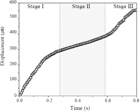
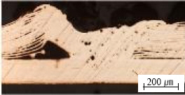
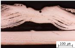
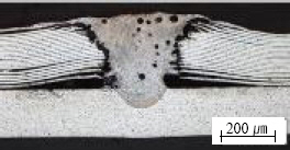
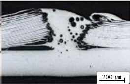
Fig.┬Ā5
The cross-section images of samples, (a) welding time of 0.2 s (b) welding time of 0.4 s (c) welding time of 0.6 s (d) welding time of 0.8 s26)
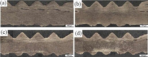
For a welding time of 0.2 seconds, there were noticeable gaps observed at the second interface, and no joint was formed. At 0.4 seconds, joints formed on all interfaces, but the mechanical interlocking was limited, resulting in weak joint strength. At 0.6 seconds, the nickel plating began to deteriorate due to interfacial friction, leading to copper-to-copper bonding. By 0.8 seconds, the nickel plating was fragmented with rough particles observed due to recrystallization. Fig. 6 provides a schematic of the joint formation process at each layer of the multi-layered structure, which is, similar to Fig. 4, divided into three stages of ultrasonic welding (S1, S2, S3).
Fig.┬Ā6
Joint formation at top, middle, and bottom interfaces and optical micrograph of a sample produced at 600 J using the small tip25)
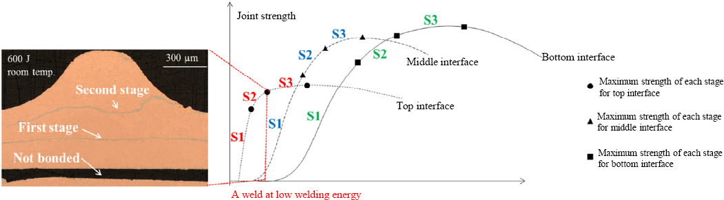
Bond formation at the interface undergoes these three stages, but they are not simultaneous in occurrence. At the upper interface, due to increased plastic deformation and temperature rise, the three stages of ultrasonic welding commence even at lower welding energies. The duration of each stage is short, making them challenging to observe. The middle interface requires more welding energy to start the first stage (S1) compared to the upper interface. Conversely, the lower interface necessitated the highest welding energy for all stages when compared to the upper interface.
In multi-layered plates, the bonding process should consider that bonding propagates through different interfaces and should encompass both interfacial bonding and mechanical interlocking11,12).
Zhao et al.27) conducted ultrasonic welding on three 0.2 mm thick copper sheets and a 0.9 mm thick sheet to enhance battery quality and cut costs, employing K- type thin film thermocouples (TFTC) and K-type thin film thermopiles (TFTP) for real-time temperature observations. By positioning micro-sensors atop the busbar and incorporating slots in the anvil to insert these sensors, they verified the three-stage theory of ultrasonic welding based on heat flux.
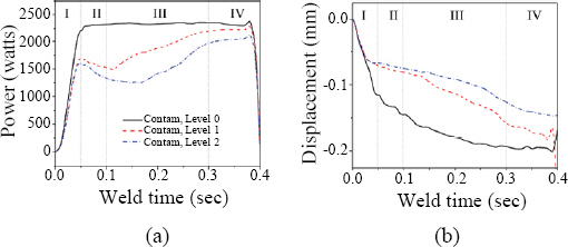
Lee et al.28) utilized two process signals, ultrasonic welding power and horn displacement, to analyze signals under abnormal process conditions where contaminants such as oil were present on the surface, as shown in Fig. 7. In stage I, materials with a clean surface showed a rapid power increase to approximately 2,300 W and maintained a stable power level throughout the welding process. However, a contaminated surface exhibited only 70-75% of the power compared to the clean surface. By stage IV, as surface contaminants were eliminated and friction resistance normalized, it stabilized. In stage I, a contaminated surface resulted in minimal material softening due to reduced output, with little to no decrease in output.
Fig.┬Ā7
Variation of (a) power signal and (b) displacement signal for different of surface contamination28)
Shao et al.29) developed a monitoring algorithm by comparing wear progression on the sonotrode and anvil surfaces during ultrasonic welding and extracting profile characteristics in the spatial and frequency domains. Since tool wear can lead to low-quality joints, potentially causing overall battery pack failures or production interruptions due to tool replacements, the framework proposed by them ensures good joint quality in battery cell manufacturing. This is achieved through tool monitoring, which provides real-time insights into the conditions of the sonotrode and anvil, ultimately reducing production costs.
3.6 Ultrasonic Welding Simulation
Shen et al.30) postulated that during ultrasonic welding, the microstructure evolution of the material is driven by severe plastic deformation, recrystallization, and thermodynamic conditions leading to particle growth. Leveraging finite element software, they simulated the ultrasonic welding of a 0.4 mm thick copper sheet with a 1 mm thick one to observe the dynamics of recrystallization and grain growth kinetics. Ultimately, they discovered that during ultrasonic welding, materials soften and, after crystal growth, exhibit a coarse and rough particle structure at the welded interface.
Samir et al.31) employed a response surface methodology to study the correlation between process parameters-such as compression force, welding time, and amplitude-and output variables, which included the power, force, and energy transmitted to the ultrasonic joint region when welding 40 layers of 37 um thick aluminum foils with a 1 mm thick aluminum sheet. The observed deviation between the actual experimental data and the simulation data was ┬▒5%. Such discrepancies are attributed to factors like the efficiency in converting electrical energy into mechanical vibrations in the oscillator, and power losses when transitioning through the sonotrode and anvil, because many ultrasonic welding processes interact with each other in rapid succession.
Lee et al.32) utilized finite element software to simulate the ultrasonic welding process for multilayered laminates. They analyzed a combination of three 0.2 mm thick copper sheets with a 1.0 mm copper sheet and another combination of three 0.2 mm thick aluminum sheets with a 1.0 mm copper sheet, aiming to simulate temperature distribution and deformation. They found that as the number of foils increased, misalignment between the sonotrode and the workpiece occurred. Frictional heat was highest closer to the sonotrodeŌĆÖs upper surface. Thin copper sheets reached a peak temperature of 400┬░C, approximately 100┬░C higher than the aluminum sheets, primarily because copper sheets have a friction coefficient of 0.30, lower than the 0.73 of aluminum sheets, leading to higher frictional energy consumption during ultrasonic welding. While these values are merely simulation estimates, experimentally measured friction coefficients provided scientific insights into the multilayered laminate ultrasonic process. Despite the existence of several numerical analyses on ultrasonic welding, thereŌĆÖs a noticeable deficit in simulations concerning multilayered laminates and dissimilar metal ultrasonic welding.
Besides simulation studies, Kang et al.33) investigated the energy loss rate due to resonance in battery cell ultrasonic welding, emphasizing that it is significantly influenced not just by process variables but also by the vibrational characteristics of the welding components and fixtures. Additionally, they developed a vibration model for the battery tab, thoroughly reviewing the impact of both longitudinal and transverse vibrations from the sonotrode horn on the metallurgical and mechanical properties of the battery tab.
4. Laser Welding of Multi-layered Foils
4.1 Laser Welding Mechanism
Besides traditional welding methods, laser welding offers the advantage of focusing a high-density energy beam onto the substrate, minimizing thermal effects and thus reducing potential damage to the surrounding areas of battery cells. This approach, when paired with automated welding systems, can enhance both productivity and efficiency34). While ultrasonic welding faces challenges as the number of foils increases, laser welding, with its high energy density and precise energy control, has fewer limitations. Recently, laser beam welding has become increasingly important in the assembly of battery cells, particularly for pouch-type batteries that consist of more than 30 layered foils. Laser welding presents a potential solution to overcome the limitations of ultrasonic processes due to its inherent benefits6). However, copper and aluminum, the primary materials of pouch-type battery cells, require high laser output levels during the keyhole process due to their high reflectivity; if the laser output isnŌĆÖt reduced after reaching peak absorption rates, excessive melting can lead to defects in the joint area35). Current research on laser welding for multi-layered foil bonding remains limited compared to studies on ultrasonic welding.
4.2 Clamping and Overlapping Configuration of Multi-layered Foils
During the laser welding of battery cell foils, similar to ultra-thin plate multi-layer welding, thermal deformations can easily occur in the plates, and minute distance changes are observed between the joint surfaces. For this reason, accurate placement and alignment of the battery cell foils, using clamping technology, is essential due to the tiny gaps that exist between multiple foils.
Grabmann et al.14) used an upper and lower support sheet attached to a clamping device to secure a stack of 40 foils. However, exerting clamping force right next to the laser welding area proved challenging due to process-related reasons, and detachment at the weld core was observed.
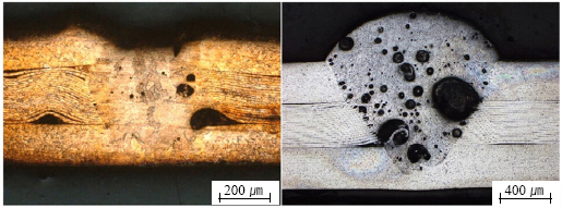
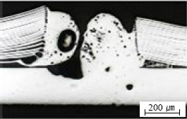
Olowinsky et al.36) employed a pneumatic clamping device and devised a sandwich configuration to position multi-layered foils between two plates, as depicted in Fig. 8. This approach aimed to prevent deformation of the multi-layered foils during welding. For a stack of 20 copper multi-layered foils, reliable bonding with the tab and a minimal number of pores were observed. However, for a stack of 20 aluminum multi-layered foils, a significant number of pores was found.
Fig.┬Ā8
Laser welding of foil stack made of copper (left) and aluminum (right) in a sandwich configuration36)
Engelhardt et al.37) placed between 5 and 30 aluminum foils in a sandwich configuration between two plates and used computer tomography, as shown in Fig. 9, to investigate the impact of foil count on porosity. The tiny amounts of air trapped between the foils are unable to escape during melting, causing varying porosity levels depending on the number of foils in the stack. At a welding speed of 10 m/min, elliptical pores larger than 5 mm2 were observed, whereas at 30 m/min, smaller but more numerous pores were observed. Compared to 5 foils, the 30-foil set exhibited a greater number of pores. The combination of high welding speed (30 m/min) and fewer foils (5) achieved a minimum porosity of approximately 5%. While the sandwich configuration proves a promising alternative, the effect of aluminum porosity on electrical conductivity needs validation.
Fig.┬Ā9
(a) Pore size distribution at different feed rates v (NL=30) with the number of counts at determined pore areas (b) Pore size distribution for different number of foil layers NL at a feed rate of 10m/min; The longitudinal cross sections show the seam porosity of the corresponding weld parameter and stack configuration37)

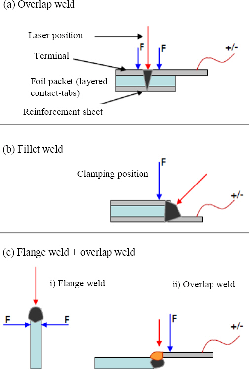
Schedewy et al.19) categorized welding configurations as A) overlap, B) fillet, and C) flange + overlap, and executed laser welding on 35 multi-layered foils (Fig. 10). Overlap welding displayed the highest strength, was easy to implement, and had good process stability. However, it was challenging to identify clamping defects between foils, making external corrections impossible. Fillet welding showed the lowest strength and was not feasible without a reinforcing sheet. The flange + overlap welding experienced instability in the second overlap welding due to thermal deformation from the primary welding. Consequently, the development of clamping devices, the number of foils, and appropriate welding joint configurations are critical parameters for achieving high-quality laser welding of multi-layered foils.
Fig.┬Ā10
Investigated weld joint configuration, (a) overlap weld, (b) fillet weld (c) flange weld + fillet weld19)
4.3 Influence of the laser wavelength spectrum
Disc lasers and fiber lasers operating in the IR wavelength range have become popular choices because of their acceptability, cost-effectiveness, and technical benefits38). Given the rising demand for batteries, thereŌĆÖs a growing interest in green and blue lasers due to their enhanced absorption rates in metals like aluminum and copper, promoting higher-quality welds35). Specifically, a heightened laser absorption rate allows for the fusion of copper and aluminum with lower power settings while also accelerating the welding process4,39). At room temperature, the reflectivity of copper stands at roughly 50% for the green laser and around 45% for the blue laser7).
Olowinsky et al.36) divided the wavelength regions into blue, green, and IR, and performed overlap welding on a homogeneous sheet of 20 multi-layered foils of copper and aluminum, as illustrated in Table 4. In the case of the blue laser, the copper foil was joined to the tab, but the foil bulged at the edge of the bead due to the limitations of the clamping device and deformation. In experiments where the green laser was applied to copper, some cases exhibited a lack of adhesion with the tab, even though the bead cross-section appeared satisfactory. For aluminum foil, both blue and green lasers achieved stable bonding only at very low speeds. With the IR laser, there were occasions when the copper foil was cut off from the weld core due to its small focus diameter of 28 ┬Ąm. Although there were observations of partial foil detachment in the case of aluminum foil, it demonstrated the potential for welding at a rapid speed of over 200 mm/s.
Table┬Ā4
Characteristics of the diode, disk and fiber laser setup and exemplary welds and cross sections for laser beam welding. (modified from ref)36)

4.4 Impact of Laser Welding Output Modes
Mohseni et al.6) utilized IR lasers to weld a copper multilayer foil composed of 15 sheets in both pulse and continuous modes, evaluating the processŌĆÖs stability and weld seam quality. Continuous mode welding exhibited greater surface roughness deviations than pulse mode welding, and droplet formation was more frequent at the weld seamŌĆÖs end section. Conversely, pulse mode had the molten area solidify more rapidly and showed significantly lower surface roughness variations, rendering it a more stable welding process.
Grabmann et al.14) employed a blue laser to weld a multilayer foil of 40 sheets, made up of copper and aluminum, to a homogeneous sheet with a thickness of 0.3 mm using pulse mode. The mechanical strength at the multilayer foil joint increased with prolonged pulse duration, higher pulse power, and increased pulse frequency, but diminished with accelerated welding speed. While stable welding was feasible on copper, in the case of aluminum, every specimen exhibited a region where the weld seam was detached from the foil. Also, this detachment location aligned with the fracture site during tensile shear testing.
Nothdurft et al.40) used an IR laser to weld a copper multilayer foil of 40 sheets to a 3.0 mm thick copper sheet and an aluminum multilayer foil of 40 sheets to a 2.0 mm thick aluminum sheet, both in pulse mode. For the copper multilayer foil, due to its high reflectivity, no successful welding process conditions were identified. Conversely, the aluminum multilayer foil showed fewer pores when pulsed at higher frequencies. However, a drawback was the prolonged processing time due to the slow welding speed of 5 mm/s. Continuous mode welding of the aluminum multilayer foil with the tab observed abundant porosity due to the increased energy per unit length and vapor pressure. For the copper multilayer foil, welding was efficient when the focus was on the foil surface, but moving the focal point inward resulted in the foil being cut and unwelded.
Grabmann el al.5) defined a multilinear regression model predicting penetration depth using millisecond pulse modulation in the blue wavelength range, with welding speed and pulse duration as input variables. This model was validated by welding copper foils of 8 ┬Ąm, 10 ┬Ąm thickness (40, 50, and 60 sheets respectively) to a 0.3 mm thick copper sheet. It was demonstrated that up to 62 sheets of the 8 ┬Ąm copper foil could be welded, and the linear regression model allowed for selecting laser process variables based on foil thickness, foil count, and tab thickness.
Grabmann et al.41) used a nanosecond pulse mode laser in the IR wavelength range to weld 40 aluminum foils to a 0.3 mm thick aluminum sheet. Welding configurations included five parallel weld seams as shown in Fig. 11 (a) and a stepped welding geometry with diagonal seams as illustrated in Fig. 11 (b). For the stepped welding geometry, they divided it into nine individual sections, tilting the weld line by 45 degrees. Fig. 11 (c) and (d) depict the height variance from the welded sectionŌĆÖs surface. While the five parallel seams saw an increase in the Y-axis height along the welding direction, leading to more significant foil displacement, the stepped welding geometry reduced thermally-induced deformations, resulting in a more uniform surface with reduced displacement. Stepped welding geometry holds promise as an alternative to increase process stability in multilayer foil welding, though further studies on mechanical and electrical properties are still warranted.
Fig.┬Ā11
(Top) Schematic description of the adaption of the welding geometry from (a) five line (b) stepped; the numbers indicate the welding sequence (Bottom) pictures of the seam surfaces the topographic heights for a welding geometry (c) five line (d) stepped41)

5. Conclusion
In this technical contribution, we aimed to compile the results of domestic and international preceding studies, elucidating the quintessential welding processes for multilayer laminates applied in pouch-type battery cells, and providing valuable data for practical research and development. While ultrasonic welding and laser welding are suited for battery cell manufacturing, quality guidelines are yet to be comprehensively established. The ultrasonic welding process, in multilayer foil welding, sees increasing challenges in horn and anvil design with the number and volume of foils; real-time monitoring technologies capable of tracking horn and anvil wear and deformations due to vibrations are in demand. The laser welding process, in multilayer laminates welding, necessitates robust clamping techniques, as the tiny gaps between surfaces form pores during laser fusion. Moreover, specific process variables like laser wavelength, output, and welding speed can vary based on battery cell design, and itŌĆÖs anticipated that ongoing research will optimize these for high-quality battery cell assembly.
 PDF Links
 PubReader
 ePub Link
 Full text via DOI
 Download Citation
 Print
Print


