1. Introduction
Various types of processes such as SPR mechanical joining or TWB laser welding are being applied as different kinds of materials including ultra-high strength steel, aluminum alloy, magnesium alloy, and composite materials are used for lightening the vehicle body; however, the welding process which is most frequently applied in the production of bodywork is still resistance spot welding. For inspecting the quality of resistance spot welded joints in the field, drive check is performed for certain spot-welded parts on the body or the nugget size is measured through full destruction. Non-destructive testing is performed using ultrasound for the parts for which destructive testing is difficult to perform. For resistance spot welding, the factors that influence the quality depending on the material and thickness of the body panel are weld current (kA), weld time (cycles/ms), and electrode force (kgf/kN); among these factors, weld current and weld time are to be set in TC used in a resistance spot welder. Electrode force used to be the major cause of weld defects as the actual electrode force could not be measured during welding when a conventional pneumatic gun is used. However, electrode force can now be controlled in real time as the pneumatic gun has been replaced with a servo gun in the field where the body is assembled, thus reducing weld defects due to electrode force
1-5) .
However, weld defects in the field still remain as the main cause of downtime during body production, and therefore, diverse inspection equipment are applied while various resistance spot welding equipment are replaced such as a medium frequency direct current (MFDC) resistance spot welder, auto tip dresser (ATD) as well as light and color sensors.
As the application of ICT and AI has emerged across the industry in recent years, many studies are being conducted on determining the quality of resistance spot welded joints through machine learning by examining the correlation between nugget and tensile strength and the changes in electrical signal patterns such as weld current and welding voltage at the secondary side of a transformer
6-7). Furthermore, using the parameters that can be collected at the welding system using a servo gun such as the encoder value according to the electrode displacement and motor current without requiring specific devices, a rising number of studies are being conducted on inspecting the quality of resistance spot welding through the evaluation of electrode wear characteristics and indentation depth measurement
3-4).
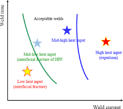
This study aimed to explore the possibility of establishing the criteria for assessing the resistance spot welding quality in real time using the equipment currently available in the field with the minimum costs, without applying new process or technology. Expansion and contraction occur during heating and cooling process of resistance spot welding, and these phenomena cause the changes in encoder values by inducing reactions to the electrodes controlled at an appropriate electrode force. Based on how the electrode displacement varies according to heat input, the lobe graph was divided into four sections with respect to heat input, low (low heat input, interfacial fracture), mid-low (normal heat input, button fracture), mid-high (normal heat input, button fracture), and high (excessive heat input, expulsion) as shown in
Fig. 1 in order to perform welding. Then, the resistance spot welding quality was assessed based on the correlation between tensile-shear strength and servo gun displacement.
Fig.┬Ā1
Lobe graph of spot-welding quality specification in the paper
2. Experimental method
2.1 Material used
For the materials in this study, the combinations of two, three, and four panels including galvanized steel plate and hot stamping steel used for manufacturing vehicle body were selected; the type and thickness of the materials are summarized in
Table 1. The chemical com- position and mechanical properties of the steel used in this study are presented in
Table 2 and
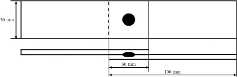
Table 3, respec- tively. As shown in
Fig. 2 below, the specimen used in a tensile-shear strength test was manufactured to be 100 ├Ś 30 mm and the overlap length is 30 mm according to the KS B 0851 standards. For the middle plate, a 30 ├Ś 30 mm specimen was used.
Table┬Ā1
Material combinations for resistance spot welding
|
Layers |
Case No. |
Materials |
Thickness (mm) |
Total thickness (mm) |
|
2 |
1 |
SPFC 980Y |
1.2 |
2.6 |
|
SPFC 590DP |
1.4 |
|
2 |
SGACUD P60/P60 |
0.7 |
1.4 |
|
SPFC 590 |
0.7 |
|
3 |
3 |
SGAFC 1180 60/60 |
1.2 |
2.9 |
|
SGACUD P60/P60 |
0.7 |
|
SGARC 440 60/60 |
1.0 |
|
4 |
SGACUD P60/P60 |
0.7 |
2.9 |
|
SABC 1470 50/50 |
1.0 |
|
SPFC 590 |
1.2 |
|
4 |
5 |
SGACUD P60/P60 |
0.7 |
4.9 |
|
SGAFC 1180 60/60 |
1.2 |
|
SGAFC 590DP 60/60 |
1.6 |
|
SGAPH 440 60/60 |
1.4 |
|
6 |
SGAFC 1180 60/60 |
1.2 |
4.7 |
|
SGACUD P60/P60 |
0.7 |
|
SGAFC 1180 60/60 |
1.2 |
|
SGAFC 590 DP 60/60 |
1.6 |
Table┬Ā2
Chemical composition of materials(wt. %)
|
Materials |
C Max. |
Mn Max. |
Si Max. |
P Max. |
S Max. |
|
SGARC 440 60/60 |
0.12 |
1.01 |
0.5 |
0.021 |
0.004 |
|
SPFC 590 |
0.09 |
1.6 |
0.15 |
0.03 |
0.003 |
|
SPFC 590DP |
0.1 |
2 |
0.2 |
0.03 |
0.003 |
|
SGAFC 590DP 60/60 |
0.1 |
2 |
0.2 |
0.03 |
0.003 |
|
SPFC 980 Y |
0.1 |
2.8 |
1.2 |
0.03 |
0.003 |
|
SGAFC 1180 60/60 |
0.17 |
2.8 |
0.25 |
0.02 |
0.005 |
|
SABC 1470 50/50 |
0.23 |
1.24 |
0.26 |
0.015 |
0.002 |
Table┬Ā3
Mechanical properties of materials
|
Materials |
0.2%YS,Mpa Spec. |
TS,Mpa Spec. |
El.,% Spec. |
|
SGARC 440 60/60 |
270~ |
440~ |
22~ |
|
SPFC 590 |
350~ |
588~ |
17~ |
|
SPFC 590DP |
~450 |
590~ |
24~ |
|
SGAFC 590DP 60/60 |
~450 |
590~ |
24~ |
|
SPFC 980 Y |
580~700 |
980~ |
15~ |
|
SGAFC 1180 60/60 |
~850 |
1180~ |
6~ |
|
SABC 1470 50/50 |
950~1250 |
1300~1700 |
6~ |
Fig.┬Ā2
Specimen for resistance spot welding
2.2 Experimental equipment
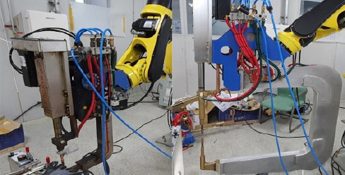
The resistance spot welder used in this study is Genius MFI 408L, which is an MFDC welder, by Harms-Wende in a KSR mode which is a constant-current control method. The welding robot is a six-axis robot BX200L manufactured by Kawasaki Robotics having a nominal load capacity of 200 kg that can obtain displacement data of each axis using the data storage function, and the electrode displacement data can be obtained by attaching a servo gun. The servo guns used in the experiment are mid-size and large-size servo C-gun designed by NAWOOTEC and currently used in the field.
Fig. 3 shows the guns attached to the robot. The stroke of the mid-size and large-size servo guns is 140 mm and 280 mm, respectively, and both types of servo guns used a 1.5 kW servo motor.
Table 4 presents the specifications of the servo motor. For electrodes, the Cu-Cr based composite electrodes having a diameter of 16 mm and a linear short diameter of 6 mm which are generally used for welding a vehicle body were used.
Fig.┬Ā3
Mid-size and large-size servo C-gun for resistance spot welding
Table┬Ā4
Mid-size and large-size servo C-gun specification
|
Mid-size C-gun |
Large-size C-gun |
|
Motor parts |
Rated output |
1.5 kW |
|
Rated speed |
3000 r/min |
|
Max. speed |
4500 r/min |
|
Rated torque |
47.98 kgf┬Ęcm |
|
Moving parts |
Ball screw lead |
25 mm |
25 mm |
|
Pulley Ratio |
0.38 |
0.4 |
|
Electrode force |
500 kgf |
350 kgf |
|
Total stroke |
140 mm |
280 mm |
|
bit resolution |
11.44409 |
12.20703 |
2.3 Experimental method
2.3.1 Experimental method
In the experiment, the data of servo gun displacement caused by expansion and contraction of nuggets generated during resistance spot welding of a total of six combinations of panels - two combinations of two layers, three layers, and four layers each - were collected. Exclusive jig and clamps were used for collecting only the data of servo gun displacement which is induced during welding depending on the change in the current. By setting five teaching points of the servo gun, ŌĆśhome - below weld - weld - below weld - homeŌĆÖ, obtaining the noise data due to vibration during welding was minimized. The welding conditions for resistance spot welding are shown in
Table 5 below. According to each panel combination, appropriate electrode force and weld time that are actually used in the field of body assembly were set. The squeeze time and cooling time were set to 200 ms and 100 ms, respectively, in order to reflect the welding conditions of the field. In order to complete a weld lobe, the weld current was increased by 0.5 kA at a time through drive check from the current at which interfacial separation occurs to the current at which expulsion occurs for welding. For securing the reproducibility of the results, welding was performed for three times at the same condition while collecting the servo gun displacement data simultaneously. Tensile-shear strength test was performed with the manufactured specimen to find the strength value, and the result was compared with the servo gun displacement data.
Table┬Ā5
Welding conditions for resistance spot welding
|
Layers |
Case No. |
Weld current (kA) |
Force (kgf) |
Weld time (ms) |
|
Mid-size C-gun |
Large-size C-gun |
|
2 |
1 |
4.0~7.5 |
4.5~7.5 |
250 |
|
2 |
4.5~8.5 |
4.0~8.0 |
|
3 |
3 |
5.0~9.0 |
4.0~8.0 |
|
4 |
4.0~7.5 |
4.0~7.5 |
350 |
233 |
|
4 |
5 |
5.5~8.0 |
5.5~9.0 |
300 |
333 |
|
6 |
5.5~9.0 |
5.5~9.0 |
2.3.2 Obtaining servo gun displacement data
To examine the changes occurred due to expansion and contraction of nuggets during resistance spot welding, the start signal of welding transmitted from the robot and the servo gun displacement data are automatically obtained simultaneously at the interval of 2 ms. The starting condition for acquiring the data was set to when the displacement decreases by less than 30 mm after the servo gun begins to pressurize. Data acquiring was automatically terminated when the data were collected for 5,000 ms.
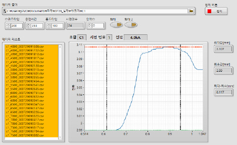
2.3.3 Servo gun displacement data analysis program
The investment cost required at the body production site is minimized, and the servo gun currently used at the site is utilized to determine the welding quality at each weld spot based on the difference between the maximum and minimum displacement which is generated due to expansion and contraction of nuggets at welding section. For this purpose, a data analysis program was developed using LabVIEW manufactured by NI that can estimate accurate starting and ending sections of heat input of servo gun displacement data and calculate maximum value, minimum value, and the difference between the two extremes. The analysis areas of the servo gun data obtained thereby included the section where current actually flows and the holding time section where cooling occurs after the current stops flowing. With respect to the point at which the welding start signal generated by the robot control panel changes from 0 to 1, predetermined variables such as squeeze, welding, and holding time as well as weld current are input so as to automatically determine the analysis scope of the servo gun data.
Fig. 5 shows process of obtaining data from the servo gun and the analysis area.
Fig. 6 shows the GUI of the developed program and the example of the acquired data.
Fig.┬Ā4
Data measuring timing diagram
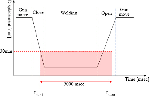
Fig.┬Ā5
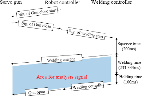
Fig.┬Ā6
Developed analysis program GUI
3. Experimental results and discussion
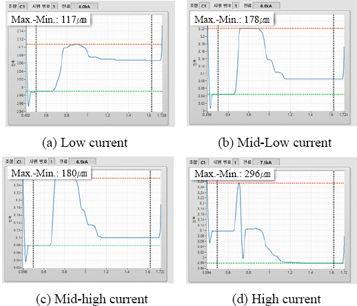
3.1 Mid-size servo C-gun for welding
For the experiment with a mid-size servo C-gun (hereinafter, the ŌĆśmid-size gunŌĆÖ), the weld lobe section was divided into low heat input (interfacial separation), mid-low heat input, mid-high heat input, and high heat input (expulsion) as shown in
Fig. 7. After extracting the maximum and minimum values of electrode displacement from welding start point to immediately after cooling time, during which welding is performed, from the displacement data obtained from each welding condition, the difference was used as the threshold value for determining the welding quality.
Fig.┬Ā7
Mid-size servo C-gun electrode displacement
3.1.1 Mid-size servo gun displacement per current section
For the six combinations of panels (1 - 6) selected in this study, the tensile-shear strength and fracture mode according to the difference between the maximum and minimum servo gun displacement values (hereinafter, the ŌĆśservo gun displacement differential valueŌĆÖ) are shown in
Figs. 9(a) -
(f). The current value used for resistance spot welding is also shown. For cases 1 - 6, the servo gun displacement differential value became greater as the heat input increased in all combinations of panels. In the high heat input condition in which expulsion (spatter) occurs, the servo gun displacement data rises sharply due to instantaneous expansion which causes the servo gun displacement differential value to fluctuate significantly as shown in
Fig. 7(d). For all the combinations, the difference in the displacement value between the mid-high heat input condition and expulsion condition is approximately 100 - 350 ŃÄø. However, in the combination 4 in which hot stamping steel is included, expulsion occurred in all lobe sections, thus confirming small changes in the servo gun displacement data depending on the difference in heat input. When the weld lobe graph was examined in terms of the fracture mode acquired from the tensile-shear test and the servo gun displacement analyzed through the welding experiment on the mid-size gun, the low heat input section below the lower limit of lobe where interfacial fracture occurs, the normal welding section, and the upper limit section where expulsion occurs could be clearly distinguished. This result contributes to the expansion of nuggets which occurs during resistance spot welding and the formation of indentation. When the weld current is applied to the specimen, thermal expansion occurs in the materials and melting occurs in the center of the electrode, followed by the expansion of a plastic zone. Subsequently, the nuggets continue to contract until the cooling time due to the electrode force applied constantly by the servo gun immediately after the maximum expansion point. Here, it is known that the nuggets are formed and the amount of displacement reduction becomes the indentation depth
8). Therefore, the servo gun displacement related to the expansion and contraction of the material exhibits the identical pattern regardless of the panel thickness or electrode force, which has been reported as the variable reflecting the process of nugget formation.
Fig. 8 shows the schematic diagram of this phenomenon. When a spatter occurs while the pressure is applied constantly by the servo motor, the servo gun displacement data rises instantly due to the increased expansion of the nugget and decreases by more than the certain displacement due to electrode force during contraction as it decreases by the volume of the separated melt.
Fig.┬Ā8
Schematic diagram of servo gun displacement by nugget expansion and contraction
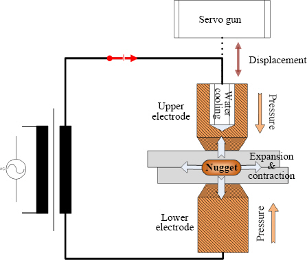
Fig.┬Ā9
Servo gun displacement, tensile-shear load and fracture mode
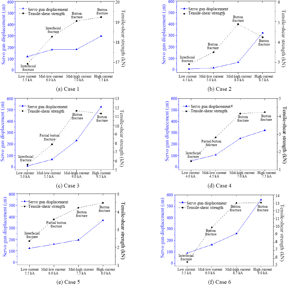
3.1.2 Correlation analysis between mid-size servo gun displacement and tensile-shear strength
When the encoder value of the robot controller during resistance spot welding was reviewed, the degree of expansion and contraction of the nuggets increased as the heat input increased, thus confirming the increase in the difference in the servo gun displacement values. Generally, in resistance spot welding, the nugget size becomes larger when heat input increases, and thus the welding strength increases. However, when the heat input exceeds beyond the normal level, the welding strength does not increase significantly due to the separation of the melt and internal defect of nuggets (pores) caused by expulsion. Likewise, in
Figs. 9(a) -
(f) which show the correlation between the servo gun displacement and tensile-shear strength, it increases linearly until the excessive heat input condition and then increases insignificantly or decreases in the excessive heat input con- dition. In contrast, the servo gun displacement value increases linearly from the low heat input condition to normal heat input condition, but it increases sharply in the excessive heat input condition where the servo gun expansion signal is generated significantly due to expulsion. The servo gun displacement and the tensile-shear strength increased linearly as the heat input increased; while the servo gun displacement increased sharply in the excessive heat input condition where expulsion occurred, the tensile-shear strength decreased or did not increase. Therefore, abrupt changes in the servo gun displacement values can be used as a variable for determining the normal heat input condition and excessive heat input condition during welding.
3.2 Large-size servo C-gun for welding
For the experiment with a large-size servo C-gun (hereinafter, the ŌĆślarge-size gunŌĆÖ), the weld lobe section was divided into low heat input (interfacial separation), mid heat input, and high heat input (expulsion) as shown in
Fig. 10 below to obtain the servo gun displacement data. Similar to the mid-size gun, the maximum and minimum values were extracted using the displacement data from the welding start point to immediately after cooling time and then the difference was examined.
Fig.┬Ā10
Large-size servo C-gun electrode displacement
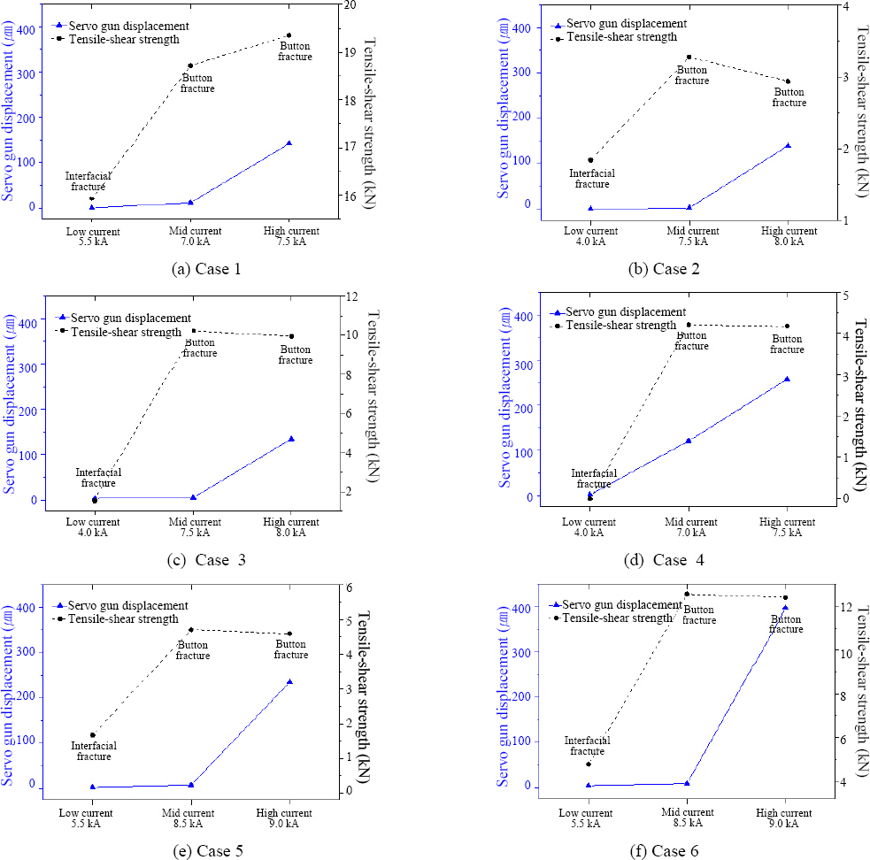
3.2.1 Large-size servo gun displacement per heat input section
For the Cases 1 - 6, the servo gun displacement differential value during welding, tensile-shear strength, and fracture mode are shown in
Figs. 11(a) -
(f). The current value used for resistance spot welding is also shown. The servo gun displacement differential value became greater as the heat input increased in all combinations of panels. In the conditions where expulsion occurs, the servo gun displacement differential value increased as it did with the mid-size gun, but low heat input of interfacial fracture and the servo gun displacement differential value in the normal condition are within several ŃÄø, thus causing difficulty in distinguishing the weld lobe section. It is difficult to distinguish the sections when heat input is low because the operating stroke of the large-size gun is 280 mm, which is twice as large as that of the mid-size gun, while the length of a motor rotation axis in the operating part of the upper gun is approximately 1,000 mm. When a servo gun is attached, the length of the upper apparatus part is increased, thereby partially playing a role of a damper. The entire force generated by the expansion and contraction of the material cannot be delivered to the motor encoder, thus causing the large-size gun to have a smaller displacement differential value than the mid-size gun. In the combination 4 in which hot stamping steel is included, expulsion occurred in all sections as it did with the mid-size gun, and therefore, the servo gun displacement differential value is 100 ŃÄø or greater even in the normal welding condition.
Fig.┬Ā11
Servo gun displacement, tensile-shear load and fracture mod
Based on the results of the large-size gun, it is deemed difficult to distinguish the low heat input section below the lower limit of the weld lobe and the normal heat input section. As mentioned before, the electrode displacement value collected from the motor encoder is further reduced than the actual value due to the size of the apparatus part of the large-size gun. However, since the high heat input condition in which expulsion occurs and the normal welding condition are clearly distinguished in the weld lobe graph, welding quality of the large-size gun can also be monitored in real time.
3.2.2 Correlation analysis between large-size servo gun displacement and tensile-shear strength
The tensile-shear strength of the specimen welded with the large-size gun increased in all combinations of panels as heat input increased as shown in
Fig. 11(a) -
(f), but the increase was insignificant or the strength decreased in the excessive heat input condition where expulsion occurred. Contrarily, the servo gun displacement value varied slightly from low heat input to normal heat input conditions but increased significantly in excessive heat input condition where expulsion occurred. Only in Case 4 shown in
Fig. 11(d), which is the combination of panels in which hot stamping panel is included, it increased linearly from low heat input to high heat input conditions. In general, tensile-shear strength before expulsion occurs is proportional to the nugget size of resistance spot welded joints, and the degree of expansion and contraction of nuggets also increases. For the large-size gun, however, the enlarged apparatus part of the servo gun played the role of a damper for the expansion and contraction of nuggets which occurred during welding as mentioned before, which resulted in the reduction in the servo gun displacement value. Therefore, the large-size gun exhibited a significant change in the servo gun displacement value in the excessive heat input condition (expulsion) as it did with the mid-size gun; even when the tensile-shear strength increases in the low to mid heat input conditions, the long length of the apparatus part worked as a damper which caused the servo displacement value not to increase significantly.
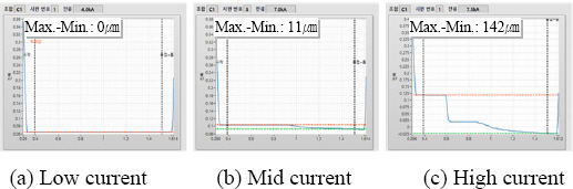
Fig. 12 and
Fig. 13 show the changes in the encoder values obtained when resistance spot welding was performed with the mid-size gun and the large-size gun, respectively. Unlike the mid-size gun, the large-size gun did not show a significant change in the servo gun displacement from when the nugget is actually expanded until the nugget formation has ended during welding. For the large-size gun, the quality difference between the low heat input and the normal heat input is difficult to distinguish, while the quality difference between the normal heat input and the excessive heat input can be clearly distinguished.
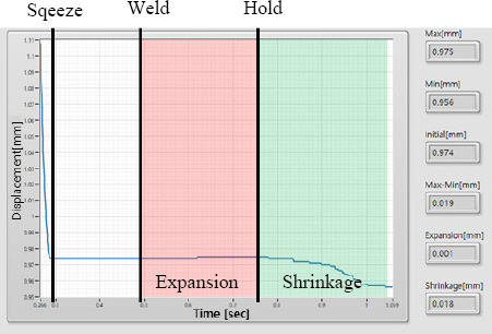
Fig.┬Ā12
Displacement of mid-size servo C-gun expansionshrinkage (acceptable condition)
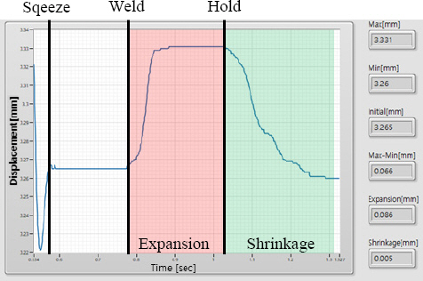
Fig.┬Ā13
Displacement of large-size servo C-gun expansionshrinkage (acceptable condition)
4. Conclusion
In this study, the data of servo gun displacement were collected according to the expansion/contraction of the materials which occur during resistance spot welding in order to determine the welding quality at the field; the following conclusions have been reached.
1) A program was developed to calculate the servo gun displacement differential value based on the sections that have been divided into interfacial fracture, normal welding, and expulsion conditions in the resistance spot weld lobe curve.
2) For the mid-size servo C-gun, the upper limit (ex- pulsion) and the lower limit (interfacial fracture and insufficient tensile strength) of the weld lobe curve could be clearly distinguished according to the heat input.
3) For the large-size servo C-gun, the upper limit (expulsion) and the normal condition of the weld lobe curve can be distinguished in limited cases due to the factor which is possibly attributable to the apparatus problem.
4) The technique for assessing the welding quality based on the servo gun displacement does not require additional devices and is expected to be used for determining the welding quality in real time with the minimum cost at the field.
Further studies will be conducted in the future on servo guns having varied structures to analyze how the mechanical structure of the servo gun affects the electrode displacement during resistance spot welding.
Acknowledgment
This study was supported and funded by Kia Motors/ Hyundai NGV industry-university research, the National Research Foundation of Korea (NRF-2017M3A9E2060430), the Ministry of Trade, Industry and Energy, and Korea Energy Technology Evaluation and Planning (No. 2018- 1510102360).
References
1. C. S. Lim and H. S. Chang, Spot Welding of Aluminum Alloys Using Servogun, J. Korean Weld. Join. Soc. 22(4) (2004) 43ŌĆō49.
2. J. Y. Baek, J. G. Lee, and S. H. Rhee, A Study of Dynamic Characteristic far Resistance Spot Welding Process Using Servo-gun System, J. Korean Weld. Join. Soc. 23(3) (2005) 40ŌĆō46.
3. Y. S. Zhang, X. Y. Zhang, X. M. Lai, and G. L. Chen, Online quality inspection of resistance spot welded joint based on electrode indentation using servo gun,
Sci. Technol. Weld. Join. 12(5) (2007) 449ŌĆō454.
https://doi.org/10.1179/174329307x207889
[CROSSREF] 5. Y. W. Park, J. G. Lee, and S. H. Rhee, A Study for the Improvement of Weld Quality Through Force Control of Servo Gun in Resistance Spot Welding using Robot, J. Korean Weld. Join. Soc. 24(6) (2006) 13ŌĆō20.
6. S. G. Choi, I. S. Hwang, M. J. Kang, and S. K. Hyun, Optimization of welding parameters in resistance spot welding of 980 MPa grade GA steel sheet using multi-response surface methodology,
J. Weld. Join. 36(4) (2018) 63ŌĆō69.
http://doi.org/10.5781/jwj.2018.36.4.7
[CROSSREF] [PDF]


 PDF Links
 PubReader
 ePub Link
 Full text via DOI
 Download Citation
 Print
Print


