1. Introduction
Plasma arc welding (PAW) is an arc welding process similar to gas tungsten arc welding (GTAW). The PAW process was invented by Robert M. Gage in the United States in 1953 and was patented in 1957 by Union Carbide Corporation in Buffalo, New York. Since then, many related patents have been applied and registered before the first PAW equipment was released in 1964. This welding equipment showed great advantages in precision welding processes for a wide range of materials with small to medium thicknesses. Its application started with methods and in directions to better control processes in low welding currents from the beginning of introduction in industries. Today, PAW provides excellent functional and technical performances in high quality bonding and table surface modification processes such as anticorrosive hard coating in small or precision applications including electronics, micro-packaging, and precision welding of surgical instruments. In particular, plasma spray coating process has been developed and applied to the wings and bodies of airplanes and the turbine blades of rockets for many years. As shown in
Fig. 1, the precision plasma bonding process is being actively applied to the manufacturing and processing of small to medium high-grade steel pipes in petrochemical plants.
Fig.┬Ā1
Smaller pipes plasma arc welding (Source: WOW Metal Co., Ltd.)
PAW is similar to GTAW in that the arc is usually formed between a non-consumable tungsten electrode made of sintered tungsten and the material to be bonded. However, a major difference between them is that in PAW the electrode is installed inside the torch body so that the plasma arc can be separated from the sphere of influence where the shielding gas is supplied inside the nozzle. Owing to this locational design of the tungsten electrode, the plasma passes through a copper nozzle in which a fine orifice is formed that shrinks the arc and allows it to flow at a fast speed close to the speed of sound and a high temperature close to 20,000┬░C.
2. Materials
2.1 Chemical Composition and Physical Properties of Materials
Recently, the standards for the emission of sulfides (Sox) in exhaust gas for vessels have been greatly strengthened. According to the enforcement of new standards applied from 2020, vessels are required to use fuels with a 0.5% or lower SOx content or install a desulfurization system to reduce the SOx emissions below the standard.
To prepare for this regulation, vessels can use low sulfur oils with 0.5% or lower sulfur or use a scrubber, which is a desulfurization device (
Table 1). Besides, emissions can be reduced by improving the operation efficiency of the vessel or by improving the new energy efficiency design index (EEDI) for vessels, but the amount of improvement cannot satisfy the standard.
Table┬Ā1
Comparison reduction method of shipŌĆÖs exhaust gas
|
Merits |
Demerits |
Remark |
|
Using 0.5% law sulfur oil |
No required Main engine modifying |
Fuel cost increase about 40% and cooling unit may required |
Uncertainty of oil supplyers, Unsettled the standard of ISO8217 |
|
Install a SOx Scrubber |
Available using fuel oil of 3.5% Sulfur content |
Required facility space(reduced cargo area), to prepare about ship waste regulation |
Installing cost: about US$3~7 million |
|
LNG Fuel propulsion system |
Remove SOx, reducible NOx and CO2
|
Required fuel tank space to be increased (reduced cargo area) |
Renovation cost:: about US$20 million |
Among the above-mentioned methods, scrubbers, which are considered to be relatively inexpensive and advantageous to manufacture and install, are often selected in the current situation.
This application case report describes the application of PAW to the fabrication and welding of a scrubber, a desulfurization device for vessels, using corrosion- and heat-resistant steel. Based on this, we aim to examine the main processes and applied technologies and to promote the development of more efficient and economical welding processes.
The material used in this welding work is 6Moly (6-6.5% Mo), which is also called a super stainless steel. Its chemical composition and physical properties are listed in Tables
2 to
5. This alloy steel has raised the pitting resistance equivalent (PRE) by chemical composition and further heightened the strength and hardness by heat treatment, and was fabricated to exhibit excellent corrosion resistance in a severe corrosive environment. In particular, 6Moly has been used in scrubbers to treat SOx from the hot emissions of vessels in a marine environment. This material is being used widely in and outside the country because it has demonstrated excellent corrosion resistance comparable to the performance of other Ni alloys and pure titanium.
Table┬Ā2
Standard comparison of materials for scrubber manufacturing
|
JIS G 4304/4305 |
ASTM A240 |
EN 10088-2/ 10028-7 |
|
6 Moly |
SUS312L |
UNS S31254 |
1.4547 |
Table┬Ā3
Chemical composition of materials for scrubber manufacturing
|
Density ŌĆāŌĆāŌĆāŌĆāŌĆāŌĆāŌĆāŌĆā[g/cm3] |
|
8.02 |
|
Specific heat ŌĆāŌĆāŌĆāŌĆāŌĆāŌĆā[J/kg┬ĘK] |
20┬░C |
464 |
|
Electrical resistivity ŌĆāŌĆāŌĆā[╬╝╬®┬Ęcm] |
|
89.4 |
|
Thermal conductivity ŌĆāŌĆā[W/m┬ĘK] |
|
12.3 |
|
Average coefficient of thermal expansion ŌĆā[10-6/┬░C] |
20~100┬░C |
15.3 |
|
20~200┬░C |
15.7 |
|
20~300┬░C |
16.1 |
|
20~400┬░C |
16.4 |
|
YoungŌĆÖs modulus ŌĆāŌĆāŌĆāŌĆā[MPa] |
|
19.7 ├Ś 104
|
|
Magnetism |
|
None |
|
Melting range ŌĆāŌĆāŌĆāŌĆāŌĆāŌĆā[┬░C] |
|
1360~1405 |
Table┬Ā4
Physical properties of scrubber
|
C |
Si |
Mn |
P |
S |
Ni |
Cr |
Mo |
Cu |
N |
|
Specification (SUS312L) |
Ōēż0.020 |
Ōēż0.80 |
Ōēż1.00 |
Ōēż0.030 |
Ōēż0.015 |
17.50- 19.50 |
19.00-21.00 |
6.00-7.00 |
0.50-1.00 |
0.16-0.25 |
|
SpecŌĆÖ (UNS S31254) |
Ōēż0.020 |
Ōēż0.80 |
Ōēż1.00 |
Ōēż0.030 |
Ōēż0.010 |
17.5- 18.5 |
19.5- 20.5 |
6.0- 6.5 |
0.50-1.00 |
0.18-0.22 |
Table┬Ā5
Mechanical properties of materials for scrubber manufacturing
|
0.2% proof stress [MPa] |
Tensile strength [MPa] |
Elongation [%] |
Hardness
[Hv] [HB] |
|
Specification (SUS 312L) |
Ōēź300 |
Ōēź650 |
Ōēź35 |
Ōēż230 |
Ōēż223 |
|
Specification (UNS S31254) |
Sheet, strip |
Ōēź310 |
Ōēź690 |
Ōēź35 |
- |
Ōēż223 |
|
Plate |
Ōēź310 |
Ōēź655 |
Ōēź35 |
- |
Ōēż223 |
|
Example |
Cold-rolled sheet 1.5mmt |
379 |
744 |
41 |
182 |
- |
|
Hot-rolled sheet 8mmt |
361 |
707 |
53 |
- |
187 |
3. Welding Work
3.1 Chemical Composition and Mechanical Properties of Materials
The chemical composition and mechanical properties of 6Moly used for scrubber welding in this study are outlined in Tables
3 and
5, respectively. As shown in these tables, this material has excellent tensile strength and elongation properties. Moreover, it contains a high ratio of Cr and 6% or higher Mo to withstand high-temperature corrosive environments with salinity and heat. Although this material has the disadvantage of higher price than stainless steel materials such as Super Duplex, its applications are increasing owing to excellent corrosion resistance and workability for welding. In particular, it has been widely used to manufacture scrubber devices that filter SOx by being installed in waste steam pipes through which exhaust gas emissions from ships are discharged.
3.2 Filler Wire
The filler wire used for welding basically has a similar chemical composition to that of the base metal and is characterized by increased contents of Mo considering high temperature and corrosion resistance of the welded parts. IN this welding, a material with sufficiently high contents of some components such as Mo was used considering the characteristics according to the work method.
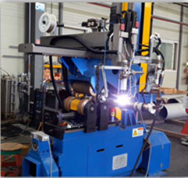
3.3 Groove Conditions and Welding Method
For the welding groove, to attain sufficient corrosion resistance of the inner part of the scrubber shell in contact with the hot exhaust gas containing SOx, a V-shaped groove (so-called Y-type groove) with a certain size of root face was maintained and the root gap was set as an air gap condition.
A typical keyhole mode was applied to the root pass and the method supplying a filler wire was adopted. After performing the root pass of the first layer in keyhole mode, the second welding pass was finished with melt-in technique. The groove angle and root surface conditions for welding joint are shown in
Fig. 2. The welding process, the completed product, and the welding bead shape are briefly shown with three photographs in
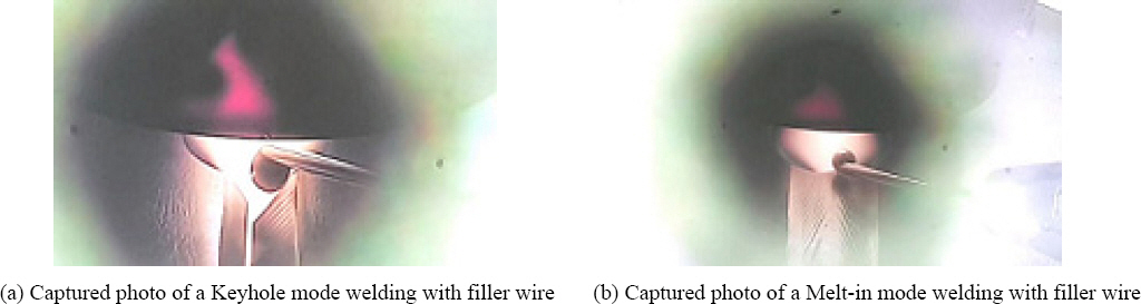
Fig. 3.
Fig. 4 shows photographs that captured the keyhole and melt-in mode used in the welding.
Fig.┬Ā2
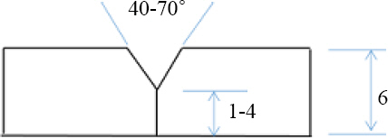
Fig.┬Ā3
Circumferential and Longitudinal welding of a scrubber shell

Fig.┬Ā4
Keyhole/Melt-in mode capture of the actual welding
3.4 Welding Conditions
The chemical composition of the wire electrode used in welding is outlined in
Table 6 and the welding conditions used are listed in
Table 7.
Table┬Ā6
Chemical composition of wire electrode
|
AWS ERNiCrMo-13 |
C |
Si |
Mn |
P |
S |
Ni |
Cr |
Mo |
Cu |
Fe |
|
*A |
0.01 max |
0.10 max |
0.5 max |
0.015max |
0.01 max |
bal. |
22.0- 24.0 |
15.0 -16.5 |
0.5 max |
1.5 max |
|
B |
0.01 |
0.03 |
0.2 |
0.003 |
0.003 |
60.0 |
23.0 |
15.6 |
0.01 |
0.4 |
Table┬Ā7
Welding parameters for PAW
|
No. of pass |
Filler metal |
Polarity |
Current (A) |
Voltage (V) |
Travel speed (cpm) |
Interpass temp. (max) |
Heat input (kJ/cm) |
|
AWS |
Dia. (mm) |
|
1st(root) |
ERNiCrMo- 13 |
1.2 |
DCEN |
250-350 |
28-32 |
38-50 |
100┬░C |
8.4-17.6 |
|
2nd(final) |
DCEN |
250-350 |
28-32 |
38-50 |
4. Welding Result and Discussion
In this welding work using PAW, the diameter of the main body of the scrubber for ships is approximately 2,300-5,000. Thus, the space is large to allow welding either inside and outside according to the work conditions. In order to attain the sufficient corrosion resistance of the inside of the scrubber through which exhaust gas passes through as mentioned above, welding from the inside to the outside is somewhat more advantageous, but outside welding may be required depending on the type of welding device or the work environment.
When welding is performed from the outside, fine and uniform backside weld beads can be expected for the welding route, that is, the inside. Here, it can be completed with single pass in I-groove with no bevel processing or root gap for up to 10-12 mm of material thickness. However, considering the bead shape and the loss of alloys in the root part, a Y-groove was created, and a good filler wire with a better corrosion resistance performance than the base metal was melted and added to the root part, thereby improving the molten metal flor and achieving stable corrosion resistance of the root part (
Fig. 4a).
Fig. 4 shows captured images of the video that was taken in keyhole and melt-in mode of the actual weld zone.
4.1 Corrosion resistance of Weld Zone
Fig. 5 shows the production test specimen collected from specimens that were welded under the same conditions as actual welding. The test was performed at the air temperature of 23.5┬░C and a humidity of 55.1-55.2. The temperature of the FeC13 test solution was maintained at 40┬░C for 24 h. No pitting was found in the ferric chloride pitting test and the amount of weight loss was represented as 0.0g/m
2.
Fig.┬Ā5
Photo of corrosion test(├Ś20)

Fig. 5 below shows a photo of the corrosion test.
4.2 Appearance Quality of Beads
The table surface and back welding beads and overall appearance were uniform and smooth because of automatic welding. Fine beads were formed to the extent that the nipples on the table surface were hard to observe. In particular, the back beads were much smaller than for TIG welding due to the absence of root gap and a narrow long arc (see
Fig. 3).
Therefore, additional work such as grinding of the welding beads is not necessary, except in special cases.
4.3 Productivity of Welding
Although the scrubber is large due to its structure, it has a moderate weight and a small thickness. Hence, when working with the scrubber lying on its side, it is not easy to apply automatic welding due to deflection and vibration by self-weight. Therefore, PAW was compared with manual TIG welding, because it is used mostly for scrubber manufacturing in South Korea (see
Table 3). As shown in
Table 8, the total welding time of PAW for the same welding field is approximately 1/7 level of manual TIG welding, showing a significant difference in welding productivity. This is because the area of the PAW groove cross-section is small, about 1/4 of that of TIG welding (one side V, groove angle 60┬░, root gap 2-3 mm), which is approximately 20 mm
2 and PAW has a welding speed of about 4 times faster. Since the welding time is relatively short, the amount of welding material consumption is also small, and the total shielding gas consumption is much smaller. However, the reason that the consumption of purge gas Ar has a very large difference is that a local purge device could be used due to welding characteristics as well as welding time.
Table┬Ā8
Welding productivity of PAW
|
GTAW(manual) |
PAW(auto.) |
|
Weld length |
43,400 mm |
|
No. of pass |
3 |
2 |
|
Travel speed |
80-100 mm/min |
400-450 mm |
|
Welding time |
21.7 hr |
3.3 hr |
|
Wire consumption |
15.6 kg |
2.2 kg |
|
Gas consumption |
345 liter |
26 liter |
5. Conclusion
1) PAW is easy to control because the arc length is long enough and also has an advantage in filler wire supply method.
2) Stable beads could be formed with a smooth weld penetration to the back of the material to be welded even in the butt joint condition without a root gap.
3) The assembly time for maintaining the root gap could be significantly shortened, and it was easier to control the welding angular deformation owing to a groove with no root gap.
4) The limited thickness range for single-sided welding work could be expanded by welding keyhole mode and melt-in mode in Y-type groove when a special control of the welding root or the material thickness exceeds the single pass welding range.
5) In general, an increase in cost is inevitable to establish a welding process that satisfies both quality and productivity when the precision of the object to be welded is critical. This study confirmed the importance of expanding the working and application technologies of PAW as a powerful welding process that can achieve welding productivity while reducing the cost.


 PDF Links
 PubReader
 ePub Link
 Full text via DOI
 Download Citation
 Print
Print


