Study on the Comparison of Electron Beam Welding and Hybrid Laser-Arc Welding of Thick High-Manganese Steel Plate for Cryogenic Applications
Article information

Abstract
Environmental protection policies have led to a focus on clean energy from Liquefied Natural Gas (LNG) and thus, its demand is increasing. Several studies for the development of cryogenic materials and fabrication technologies for storage and delivery of LNG are presented worldwide. Recently, International Maritime Organization (IMO) acknowledged that high-manganese steel was one such cryogenic material for application in LNG storage. Thus, high-manganese steel is expected to be increasingly used in the cryogenic storage industry because of its excellent material properties such as low-temperature toughness and tensile strength. A variety of researches on the welding technologies are available, including arc welding, laser welding and hybrid laser-arc welding. However, electron beam welding (EBW) has not been widely studied. In this work, EBW was investigated for the thick high-manganese steel plate and its mechanical properties were evaluated and compared with the characteristics of hybrid laser-arc welding. Our study indicates that EBW exhibits better mechanical properties than the hybrid laser-arc welding and it can be an effective potential candidate technology for welding of thick high-manganese steel plate with application in cryogenic storage tank.
1. Introduction
The global demand for liquefied natural gas (LNG), recognized as a clean energy source, is on the rise in alignment with environmental protection policies1,2). LNG, a condensed form of hydrocarbon fuel primarily composed of methane (CH4), offers a practical solution for the transport and storage of natural gas. The lique- faction process involves cooling natural gas to -163°C, significantly reducing its volume to 1/600 compared to its gaseous state, facilitating storage and transportation. Ongoing research and development efforts focus on securing manufacturing technology for the storage and transport of cryogenic materials, particularly LNG3-5). The International Maritime Organization (IMO) has approved only four types of materials for cryogenic LNG tanks: nickel alloy steel (Fe-36Ni), stainless steel (Fe- 18.5Cr-9.25Ni), 9% nickel steel (Fe-9Ni), and aluminum alloy (Al-4.5Mg). However, challenges related to the unstable supply and high costs of nickel have prompted the exploration of alternative materials. POSCO has successfully developed a high-manganese steel, offering a cost-effective solution with excellent toughness and tensile strength compared to conventional materials6,7). Notably, the IMO’s recent approval of high-manganese steel for use in cargo and fuel tank vessels is expected to further enhance the adoption of this material (Table 1).
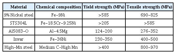
Materials for cryogenic fuels listed in the IGC code
High-manganese steel, approved by international standards, has prompted research into welding technologies suitable for LNG storage tanks. Various welding methods, such as shielded metal arc welding (SMAW), gas tungsten arc welding (GTAW), submerged arc welding (SAW), and flux-cored arc welding (FCAW), have been explored8-10). However, traditional arc welding methods have drawbacks, including groove machining, filler material usage, multi-pass multilayer welding, high heat input, and thermal deformation. To address these challenges, alternative approaches like laser welding and hybrid laser-arc welding have been investigated11-13). First, a double-sided butt-welding study using a 15 mm thick high-manganese steel (22-26Mn) specimen and a 5-kw fiber laser was published12). In optimized process conditions (4 to 5 kW, 0.5 to 0.75 m/min), yield strength and tensile strength averaged 496.7 MPa and 838.2 MPa, respectively, which are 97.5% and 93.5% higher than that of base metal. Next, a 15 mm thick high-manganese steel (24.291Mn) specimen was butt-welded using hybrid laser-arc welding technology. The process was optimized with a laser power of 14 kW, a welding current of 300 A, and a welding speed above 1 m/min, and the yield strength and tensile strength averaged 516.2 MPa and 838.8 MPa, respectively. These values are excellent, 110.5% and 96.8% compared to the base metal, respectively13).
Compared to laser-based welding technologies, the electron-beam welding (EBW) technology can weld thick plates by one pass at a fast speed, with such advantages as lower heat input, lower residual pressure, and smaller heat-affected zone (HAZ)14-16). However, the EBW technology has a disadvantage that the size of the welded specimen is limited by the dimensions of the vacuum chamber. Recently, local vacuum electron beam equipment technology has been developed to enable the application of EBW technology at a low cost to large mechanical components17,18). Consequently, EBW technology has the potential to be considered as a welding technology for large ultra-low-temperature machine parts (e.g. storage tanks). However, the study of EBW for high-manganese steel is still insufficient. The result of an EBW study of high-manganese steel was first published in 202319). A 12 mm-thick high-manganese steel (25.98Mn) material was welded by one pass, with a tensile strength of 605 MPa. This is a very low value corresponding to 81.2% compared to base metal (745 MPa). However, the IGC code requires 800 MPa and 660 MPa or more for the tensile strengths of the highmanganese steel base metal and weld area, respectively. Thus, the tensile strengths of high-manganese steel base metal and weld area in recent studies do not meet the standards of the IGC code. Therefore, EBW research using specimens that meets the IGC code standards is needed.
This study conducted EBW and weld area tests of 15 mm thick high-manganese steel materials and compared the results with previously published hybrid laser-arc welding results. The electron beam process variables were examined using a bead welding test and applied to butt welding. In particular, to evaluate the mechanical properties of the EBW according to the welding speed, the tensile strength, cryogenic impact, and microhardness of the weld area were tested at different welding speeds (1000, 1200, 1500 mm/min). Furthermore, the electron probe microanalyzer (EPMA) analysis was also performed to determine the loss rate of manganese according to the welding speed. This study verified the applicability of EBW technology to high-manganese steel, addressing the need for research to develop alternative materials and welding methods in LNG storage tank construction.
2. Used Materials
2.1 Used Materials
Table 2 shows the chemical composition of the highmanganese steel base metal used in EBW. The quantitative values for chemical composition were measured using optical emission spectroscopy. The manganese content is approximately 25.815%, and it is an austenitic stabilizing element like nickel. Chromium improves corrosion resistance, and it was added to a minimum because it is a ferrite stabilizing element. This study used a 15 mm thick specimen (approximately 150 mm×400 mm) to directly compare the welding properties with the recently published hybrid laser-arc welding experiment13).
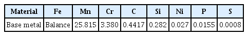
Chemical composition of the high manganese steel (wt%)
3. Experiment Method
3.1 Electron Beam Welding (EBW)
In this study, two high-manganese steel plates were butt-welded in longitudinal direction using a 120 kV (120 kW) electron gun. To compare the welding characteristics at the same welding speed as hybrid laser-arc welding, the EBW speed was set to 1000 mm/min. The optimized current value derived from the bead welding test was 48 mA, which corresponds to 5.76 kW when converted to power. Using the advantages of the electron beam, additional welding specimens were fabricated at 1,200 and 1,500 mm/min to compare welding properties at faster speeds. The optimized current values of 54 and 73 mA were used, respectively, which correspond 6.48 and 8.76 kW, respectively, when converted to power.
3.2 Analysis of the Specimen’s Cross Section and Elemental Composition
An optical microscope (OM) was used to take macro photographs of the EBW specimen sections and measure the length of the millimeter scale. The OM was mainly used to measure the weld bead width and the length of the HAZ, and the VHX-7100 model from KEYENCE was used. The field emission type scanning electron microscope (FE-SEM) and electron probe microanalyzer (EPMA) were used to analyze the microstructure and components of the weld area. Qualitative analysis was performed with FE-SEM to determine the manganese content of the base metal and the loss rate of manganese in the weld area, and quantitative analysis was performed with the EPMA. The SU7000 model from HITACHI and the JXA8530F model from JEOL were used for FE-SEM and EPMA, respectively.
3.3 Mechanical Properties Test
Microhardness test, tensile test and cryogenic Charpy impact test were performed for each specimen (hereinafter referred to as V1000, V1200, and V1500 specimens) with welding speeds of 1000, 1200, and 1,500 mm/min to examine the mechanical properties of the EBW area. To analyze the hardness of the EBW area and HAZ, a microhardness test was performed using the HM200 model from MITUTOYO. The specimens were polished to 1 ㎛ before the test, and etching was done to verify the position of the indentation after the test. For reference, the test conditions used were a load of 0.1 kgf, a duration of 15 s, and a measurement interval of 50 ㎛. The tensile test complied with the code of ASME IX QW-150:2021 and the equipment used was the UH-F500kNI model from SHIMADZU. For reference, the speed used for the tensile test was 18 mm/min. The cryogenic Charpy impact test complied with the code of ASME IX QW-170:2021 and the equipment used was DTI-603B of Daekyung Tech. The dimensions of the impact test specimen were 10 mm high, 10 mm wide, and 55 mm long. In addition, a 2 mm “V” notch and an 8 mm hammer were used. In particular, the absorbed energy value was obtained with three specimens from the upper, middle and lower areas of the EBW specimen’s cross-section.
4. Discussion
4.1 Analysis of the EBW Specimen’s Cross-section
Fig. 1 shows the cross-section images of specimens welded with a voltage of 120 kV at welding speeds of 1000, 1200, and 1500 mm/min, respectively. The bead welding test derived appropriate process conditions, and a current of 48 mA was used when the welding speed was 1,000 mm/ min (V1000) (Fig. 1(a)). As explained above, the welding speed of 1000 mm/min was used to compare welding properties directly with the results of hybrid laser-arc welding. Subsequently, welding was performed by increasing the welding speed to 1200 (V1200) and 1500 mm/min (V1500) and increasing the current volume by 20 and 50% (57 and 73 mA, respectively) in proportion to the increase in speed. As a result of precise analysis of the cross-sections, no welding defects such as pores and cracks were found.
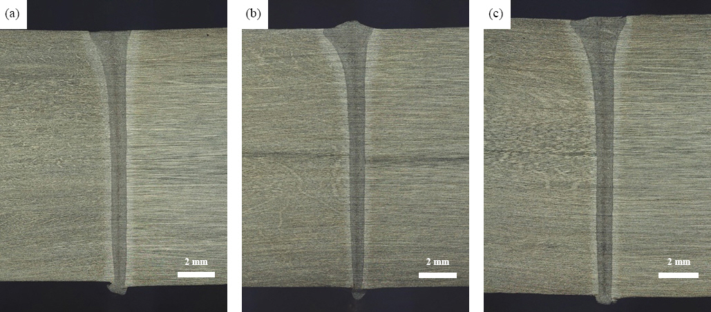
Cross-section images of EBW specimens. Welding speed of (a) 1000 mm/min (V1000), (b) 1200 mm/min (V1200), and (c) 1500 mm/min (V1500)
Fig. 2 shows the mid-section of the specimen in Fig. 1 photographed with an optical microscope at 50 and 400 magnifications. All three welding speed conditions showed similar bead widths (~900 ㎛) and HAZ sizes (300 to 400 ㎛), and dendrite growth tissues were observed.
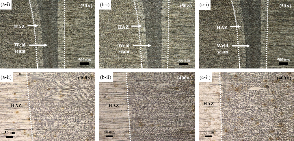
Magnified cross-section images of EBW specimens. 50× and 400× images of (a) V1000, (b) V1200, and (c) V1500
Fig. 3 shows the results of FE-SEM analysis of the V1000 specimen’s cross-section. Fig. 3 (a) shows 60× magnified images of the boundaries of the weld area and HAZ. Due to dendrite growth, the boundary of the weld area was clearly separated from the HAZ of the base metal. Fig. 3 (b) shows a 1,000× magnified image of the weld area, and dendrite growth tissues can be identified. EDS line analysis was performed at the boundary to qualitatively determine the elemental compositions of weld area and HAZ. Fig. 3(c) shows the result of an EDS analysis of the Fe, Mn, and Cr contents in the weld area at 700 ㎛ and the base metal area at 700 ㎛ (red dotted line in Fig. 3 (a)). A slight decrease in Mn content in the weld area was observed. A slight loss of Mn in these weld areas is similar to the previously published results of laser welding properties11) Fig. 3(d) shows the result of EDS point analysis at positions #1 to #4 of Fig. 3(b). The observed average weight percentage cents (wt%) of Fe, Mn, Cr, and Si were 75, 21, 3.2, and 0.6%, respectively. For reference, the analysis uncertainty of EDS was approximately 6%, and the wt% value can be referenced from a qualitative point of view.
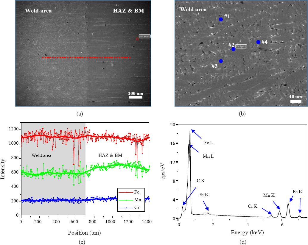
SEM and EDS analysis of V1000. (a) SEM image (60×) of interface between weld metal and HAZ area, (b) SEM image (1000×) of Weld metal, (c) EDS line profile between weld metal and HAZ area, (d) EDS elemental analysis of Fe, Mn, Cr, and Si
Quantitative analysis was performed using EPMA to analyze the loss rate of Mn in the EBW area. Fig. 4 (a) to (c) show the backscattered electron (BSE) images of the EBW specimen. For each specimen per welding speed, a line analysis of the Mn element was performed in a 1.6 mm section including the weld area (~900 ㎛) and the results are compared in Fig. 4d. In all three specimens, the Mn content in the weld area was widely distributed between 20% and 30% around 25%. To analyze the cause of the variable content of Mn, a mapping analysis was performed in the 3000× magnified area (Fig. 4(e)) of the V1000 specimen. The mapping results of Fig. 4(f) indicate that the Mn content is concentrated at the interdendritic (ID) region and that there is less Mn in the dendritic core (DC). To quantitatively compare the Mn contents in the ID and DC regions, a point analysis was done and the results are summarized in Fig. 4(g). The ID regions (#1 to #3) yielded 26.1, 27.6, and 30.1%, which are higher than the Mn content of base metal. In contrast, the DC regions (#4 to #6) yielded 22.9, 21.0, and 22.8%, which are lower than the Mn content of base metal. Thus, it can be concluded that Mn segregation occurred at the ID region when Mn was melted and solidified in the weld area. These results are consistent with the recent EBW study on high-manganese steel19). From the results of Fig. 4, we could identify the reason that the Mn contents in the line analysis differed significantly depending on the position.
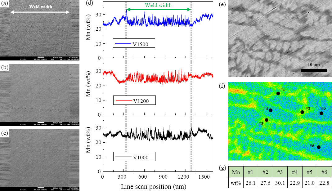
EPMA analysis of EBW specimens. BSE images (100×) of (a) V1000, (b) V1200, and (c) V1500, (d) Line profile data of Mn (wt%), (e) BSE image (3000×) of weld area of V1000, (f) Mapping image of Mn (wt%) of (e), (g) Mn (wt%) of #1~#6 in (f)
Fig. 5 shows the result of mapping the Mn contents for EBW specimens V1000, V1200, and V1500, respectively at the boundary (400 ㎛×400 ㎛) of the EBW area and base metal. Fig. 5 (a) (i) and (ii) show BSE photographs and mapping results for the V1000 specimen. While the Mn contents in the weld area were similar, a relatively uneven Mn contents were identified in the base metal. In the mapping image of (ii), the Mn content in base metal areas #2 and #3 were 26.7 and 24.4%, respectively. This suggests that the Mn content may vary from one area to another. The Mn content in the large area #4 of the base metal was found to be 25.9%, and a direct comparison of #4 and the weld area (#1) shows that the weld area contains slightly less Mn. This trend showed the same results in the specimens V1200 (Fig. 5(b)) and V1500 (Fig. 5 (c)). As a result, the Mn content in the EBW area ranged from 24.5 to 25.2% (based on #1), while the Mn content of base metal ranged from 25.5 to 25% (based on #4). Thus, within the scope of the results of this study, there was little loss of Mn in the high-manganese steel weld area to which the EBW technology was applied. Further- more, no differences in material properties were observed at the EBW speeds of 1,000-1,500 mm/min.
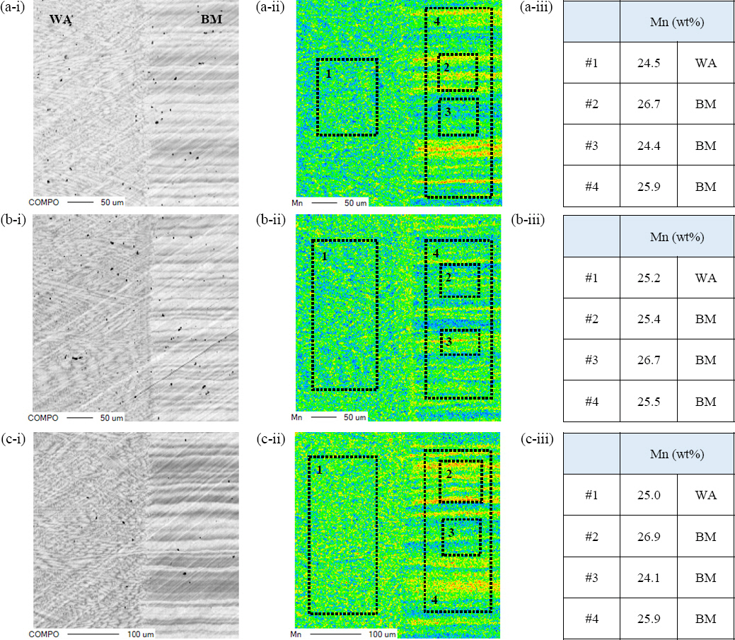
EPMA analysis of EBW specimens. (a) V1000: (i) BSE and (ii) mapping image of interface between weld area (WA) and base metal (BM). (iii) Mn (wt%) of #1~#4 in (ii), (b) V1200: (i) BSE and (ii) mapping image, (iii) Mn (wt%) of #1~#4 in (ii), (c) V1500: (i) BSE and (ii) mapping image, (iii) Mn (wt%) of #1~#4 in (ii)
4.2 Mechanical Properties Test of EBW specimens
Fig. 6 shows the results of the microhardness test in the middle part of the specimen in Fig. 1 (at 8 mm position on the surface). In consideration of the small welding bead and HAZ, a load of 0.1 kgf (maintained for 15 seconds) was used and test was conducted in a total range of 3 mm (1.5 to +1.5) at intervals of 50 ㎛. For reference, fine polishing was performed to 1 ㎛ before the test, and etching was done to verify the position of the indentation after the test. Fig. 6 (a) to (c) show optical microscope images indicating the positions of the edge welding bead and indentation. About 17 indentation points in the weld area and about 5 indentation points in the HAZ were observed. Fig. 6 (d) shows a graph with the results of the microhardness test for 60 indentations. It can be seen that the hardness value in HAZ is slightly higher than in the weld area. In the case of the V1200 and V1500 specimen, however, unusual parts were found which showed too high hardness values in general compared to the base metal. For this reason, an additional microhardness test was performed at a distance of 15 mm from the weld area. Fig. 6 (e) shows the hardness values in the range of -15 to +2 mm. The farther away from the weld area, the lower the hardness was. But the V1500 specimen still showed higher hardness values than the base metal. It is assumed that as the welding speed increased, the tissue became dense and the hardness increased relatively due fast cooling. For reference, the hardness value of the V1000 specimen showed similar results to that of the hybrid laser-arc welding specimen (at the same speed).
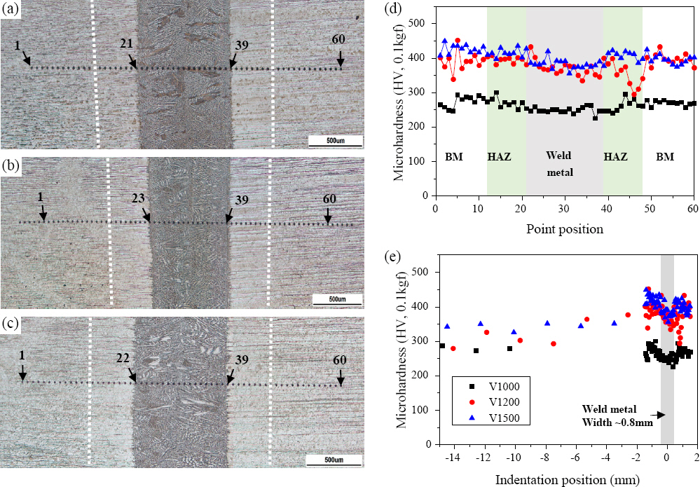
Microhardness analysis of EBW specimens. Optical images of indentation position of (a) V1000, (b) V1200, and (c) V1500, Scale bar = 500 um, (d) Comparison graph of microhardness tests at 60 points (between -1.5 and 1.5 mm), Black, red, blue colors are V1000, V1200, and V1500, respectively, (e) Comparison graph of microhardness from -15 to 2 mm
Fig. 7 shows the result of the fractured specimen and strain-stress curve after the tensile test of the EBW specimen. For the V1000, V1200 and V1500 specimens, five specimens were processed each and a stretch test was carried out for the reliability of the test results. Referring to Fig. 7 (d) (V1000), all five tests showed similar trend curves and tensile strength results. Furthermore, the maximum tensile strength values of specimens (Fig. 7(e) and 7(f)) for which the welding speed was improved by 20 to 50% only increased slightly, and the curves showed highly similar trends. These results are thought to be due to the fact that the heat input received by the material is similar because the fast welding speed increased the current amount by 20 to 50%.
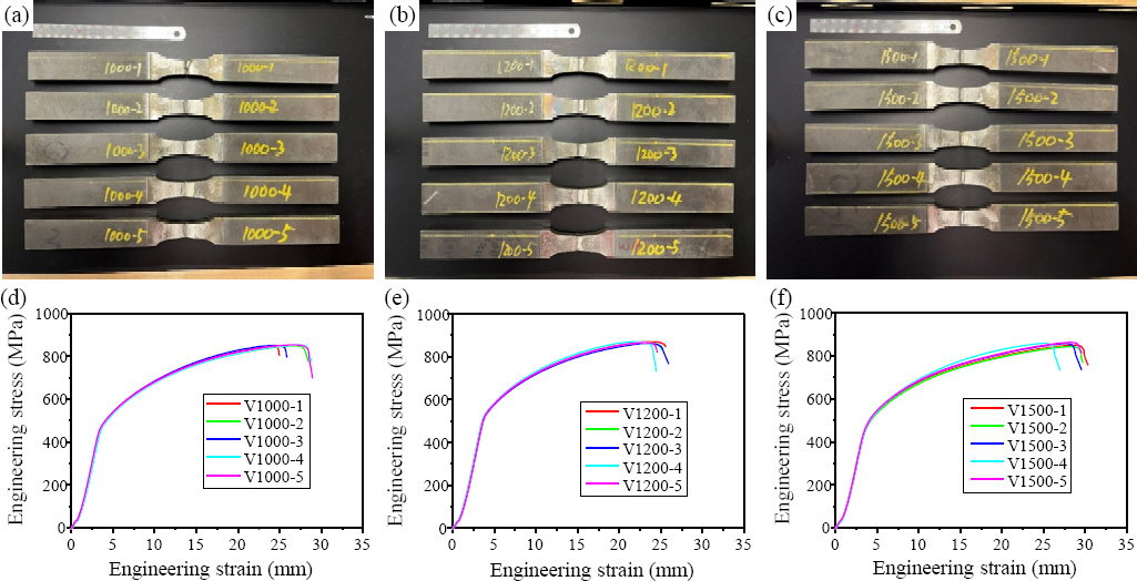
Photos of tensile strength specimens of (a) V1000, (b) V1200, and (c) V1500, Strain-stress curves of (d) V1000, (e) V1200, and (f) V1500
Fig. 8 shows the results of quantitative tensile strength comparison based on the strain-stress curve result of Fig. 7. The tensile strength averages for the V1000, V1200, and V1500 specimens were 851.2, 868.0, and 854.8 MPa, respectively. For each tensile test result, the maximum-minimum-average values are shown in Fig. 8 (d). The tensile strength of the base metal was compared with that of the hybrid laser-arc welding specimen. As a result, the tensile strength of the EBW specimen tested in the present study is highly similar to the tensile strength (average 873.2 MPa) of the base metal. The difference between the tense strength averages of base metal and the tensile strength average of the EBW specimen is 1 to 3%. Thus, taking into account a slight measurement error of each specimen, the EBV test results can be predicted as a fracture of the base metal or HAZ. Meanwhile, in the previously published hybrid laser-arc welding study, the tensile strength was 818-859 MPa (at 1000 mm/min), which is smaller than that of the EBW specimen, and the fracture occurred in the weld area. Thus, within the range of the process conditions adopted in the study, the EBW was 1.5 times faster than hybrid laser-arc welding and had a larger tensile strength.
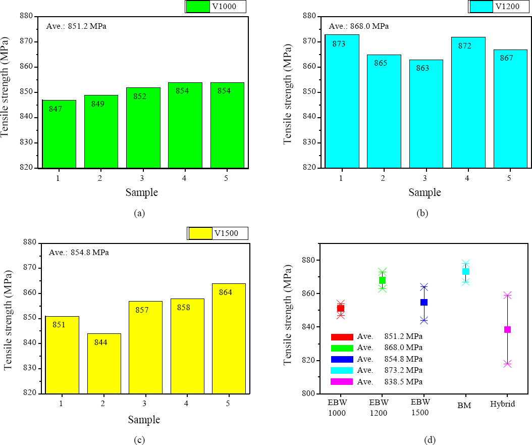
Graphs of tensile strength tests of (a) V1000, (b) V1200, and (c) V1500, (d) Comparison graph of tensile strength tests of EBW, hybrid laser-arc welding, and base metal
Fig. 9 shows photographs of the top, side, and root of the fracture after the tensile test of the EBW specimen. In Fig. 2, the welding bead width and HAZ are ~900 ㎛and 300-400 ㎛ respectively. In Fig. 9 (a), the fracture that occurred in the HAZ and root base metal at the top of the weld area appears to have continued. In contrast, Fig. 9 (b) shows a fracture that occurred in the upper HAZ and root base metal, which unusually crossed the weld area. Furthermore, in Fig. 9 (c), it is thought that a fracture occurred in the HAZ when the narrow welding bead is considered. Thus, we can conclude that the tensile test results in Fig. 8 are consistent with the fracture photographs in Fig. 9.
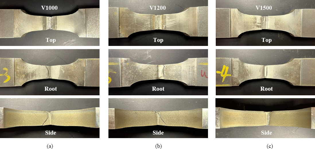
Photos of fractured tensile specimens of (a) V1000, (b) V1200, and (c) V1500
Fig. 10 shows the results of the cryogenic Charpy impact test. The impact test was carried out by preparing three specimens each at the top, middle and root based on a thickness of 15 mm of the high-manganese steel specimen. In the previous tensile test results, the V1200 and V1500 specimens showed higher tensile strengths than the V1000 specimen, while the impact test showed the highest absorbed energy in the V1000 specimen.
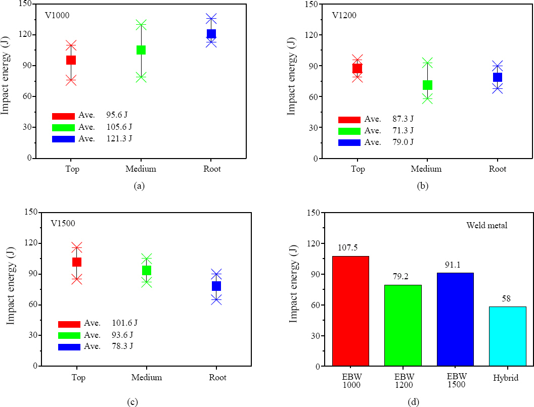
Cryogenic charpy impact tests of (a) V1000, (b) V1200, and (c) V1500, (d) Comparison graph of impact energy tests
For reference, the bead width of the EBW specimen is very small, so it is difficult for a hammer blade to impact exactly the same weld area. Thus, it is difficult to objectively compare the absorbed energy according to the EBW speed, but it was generally slightly higher than the absorbed energy of the hybrid laser-arc welding specimen. According to the IGC code, the absorbed energy required for the impact test must be 27 J or higher (at -196°C). Therefore, both EBW and hybrid laser-arc welding shock tests sufficiently satisfy the code requirements.
5. Conclusion
This study analyzed the welding properties by performing electron beam butt welding of high-manganese steel, as a cryogenic material. Tensile test, cryogenic Charpy impact test, and microhardness test were performed to test the mechanical properties of the weld metal and the results were compared with the results of a recently published test of hybrid laser-arc welding specimens. Furthermore, mechanical properties tests and material analysis were conducted while changing the welding speed of electron beam, and the following conclusions were obtained.
1) The EBW characteristics were used at a welding speed of 1,000 mm/min to compare them with the hybrid laser-arc welding characteristics under the same conditions. The tensile test results of the EBW specimen yielded an average of 851 MPa, which is similar to the tensile strength of the base metal. Furthermore, the result of fracture analysis indicates that the crack started mostly in the HAZ. For reference, the hybrid laser-arc welding specimen had an average tensile strength of 838.5 MPa, and the rupture occurred in the weld metal. The cryogenic Charpy impact test results showed that the tensile strength of the EBW specimen was approximately 1.8 times higher than that of the hybrid laser-arc welding specimen. In terms of heat input, the power of the electron beam was 5.76 kW. The hybrid welding used a laser of 14 kW and a welding current of 300 A.
2) To demonstrate the possibility of EBW at faster speeds, the welding specimens were prepared at the speeds of 1200 and 1500 mm/min. The tensile test results yielded 868 and 854 MPa on average, respectively, and a fracture was observed in the HAZ. For reference, when the speed of 1500 mm/min was used, the power used was 8.76 kW, or 7.3% of the equipment specification. Thus, it is estimated to be more than 2,000 mm/min of welding speed could be utilized for electron beam welding. When the welding speed was increased, the hardness value of the weld area in the microhardness test tended to be about 400 Hv, which is high. Analysis was performed using EBSD for analysis in conjunction with the microstructure analysis, but no peculiarities were found. This requires further experimentation and analysis.
3) Quantitative analysis was performed using EPMA to determine the loss rate of Mn in the weld metal. The Mn content was 24.5 to 25.2 wt% in the EBW area, and 25.5 to 25 wt% in the base metal. Thus, the loss of Mn in the high-manganese steel weld area using the EBW technology was negligible (at the speed of 1,000 to 1,500 mm/min).
High-manganese steel materials are highly applicable in most areas that require cryogenic property (e.g. LNG propellers, LNG fuel tanks, and LNG fueling stations). The results of this study confirmed the applicability of the EBW technology for high-manganese steel materials, and demonstrated that the mechanical properties are superior to the hybrid laser-arc welding technology. Furthermore, a welding speed of more than 2000 mm/min using electron beam is considered to be feasible. However, if the EBW technology is to be applied to large structures, local vacuum EBW equipment and process optimization technology will be required, and research and development in this field will be needed in the future.
Acknowledgement
This work was supported by the Ministry of Trade, Industry and Energy’s Project of Machinery and Equipment Industry Technology Development (project number: 20012381, project name: Development of precise electron beam welding system for highend materials and parts) and the project of the Korea Institute of Machinery & Materials (KN028B). We would like to express our gratitude for the supports.