Effects of Welding Parameters on Droplet Transfer and Bead Geometry in Laser Welding with Aluminum and Stainless Steel Filler Wires
Article information

Abstract
Laser welding is increasingly used in industries because it allows high production cycle time and single-sided welding, but is characterized by a high sensitivity to joint preparation. By inserting filler wires, the sensitivity to joint preparation can be suppressed. In this study, the effect of welding variables on the bead geometry and melted droplet transfer were investigated. Two wires with different thermal diffusivities and densities were selected: stainless steel (STS) and aluminum (Al) wires. According to the wire feeding angle, the melting area tended to differ between the STS and Al wires. This implied that the wire feeding angle had to consider the absorption rate of the material for the laser wavelength. With an increase in the distance between the wire tip and the substrate, the dominant force acting on the droplet was changed from surface tension to gravity. Therefore, the distance was considered as a major factor in determining the droplet transfer mode. In all cases, the droplet transfer period exhibited relatively small deviation when the wire feeding direction was leading. Furthermore, the focal length effects on droplet transfer were irrelevant.
1. Introduction
Laser welding can be performed at high speed under a low heat input condition, but it is known to be sensitive to the gap. Since most of the laser welding process is performed in autogenous welding, accurate joint preparation is required. If the preparation of the joint is insufficient1), defects easily occur such as underfill and blowholes. This is because a small amount of molten metal formed during the process was consumed through the gap, leading to thickness loss and defect formation. The application of filler metals makes it possible to compensate the lack of thickness, inhibit the formation of defects, and provide additional properties or characteristics2).
During laser welding with filler wires, wires are melted by the laser heat source and transferred to the substrate. The transfer is classified into bridge transfer, free-flight droplet transfer, and wire short circuit transfer depending on the droplet transfer mode3-5). Transfer varies depending on variables, such as the wire feeding speed, feeding direction, distance between the wire tip and substrate, and feeding angle. Droplet transfer mode directly affects welding characteristics, such as bead geometry and spatter generation.
Zhao et al.6) mentioned that the amount of melted wire increases as increasing of wire feeding speed. Since the amount of energy transferred to the wire increases, thereby causing an increase in bead height. Syed et al.7) reported that sound weld beads without defects were secured when the wire was fed from the leading direction, while rough and fluctuated beads were formed when the wire was fed from the trailing direction. Zhao et al.8) proved that the distance between the wire tip and substrate affects the transfer mode. They confirmed that bridge transfer changed to free-flight droplet transfer as the distance increased, and proved that the bead width and penetration change depending on the transfer mode. The wire feeding angle also affects weldability because the laser beam is reflected from the wire surface. Therefore, as the wire feeding angle increases, the amount of energy transferred to the wire can be reduced9).
This study aimed to examine the effects of the wire feeding angle, feeding direction, distance between the substrate and wire tip, and focal position on transfer mode using different filler wires under fixed welding speed and laser power conditions. An attempt was also made to find welding variables that play a more dominant role when multiple factors react simultaneously.
2. Experimental setup
Stainless 304L (STS 304L, 120×110×1.0 mm) and Aluminum 5052-H32 (Al 5052, 120×110×1.2 mm) with different specific heat and thermal conductivity values were used as the substrate. Filler wires, STS 308L and Al 5356 with a 0.8 mm diameter, were selected to observe the change in transfer mode depending on the variables. The detailed properties of used materials were presented in Table 1. A fiber laser (C12000, RAYCUS) was applied as a heat source, and the focal length of the optic was 241.5 mm. During the experiment, the distance between the contact tip and the laser beam irradiation point was maintained at 15 mm. No protective gas was applied for the welding of STS, but Ar gas was supplied at 20 and 15 L/min from the front and back sides to prevent the oxidation for the welding of Al. For comparison, the laser output (2.5 kW) and welding speed (3 m/min) were fixed to maintain the heat input. As shown in Fig. 1, the focal position (Lf), wire feeding direction (Wf), wire feeding angle (θ), and distance between the wire tip and substrate (Wh) were selected as experimental variables, and details are given in Table 2.
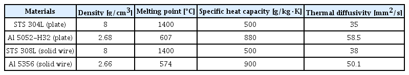
Thermal properties of used materials, plate and solid wire of aluminum and stainless steel
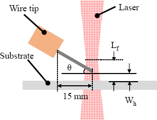
Definition of welding variables used in experiment
Variable parameters used in experiment
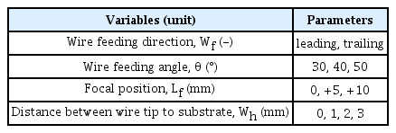
Droplet transfer was captured using a high-speed camera (FASTCAM UX 50, Photron). To obtain side view images, the camera was vertically installed at a distance of 1.2 m from the laser irradiation point (Fig. 2a and b). Laser illumination was used to obtain clear images. Imaging of droplet transfer was captured at 5,000 fps, and the 808 nm bandpass filter and ND 8 lens were mounted on the front of the camera. For imaging of the plasma plume, however, only the ND 8 lens was used. The roughness of the bead surface was analyzed using a laser scanner (LJ-X 8000, Keyence) to compare weldability after welding, and the penetration depth and cross-sectional area were also secured through cross- sectional analysis.
Schematic diagrams of high-speed camera setup from (a) side and (b) top views
3. Results
3.1 Effects of welding variables on bead formation
Bead appearance is an important factor for estimating the stability and reproducibility of the process. As process instability and internal defects increase, the difference in width and height also increases. In addition, the wettability of the droplet and the dilution rate with substrate are also important factors for estimating the weldability. In this study, constant bead height was considered as the main factor to evaluate the process stability.
3.1.1 STS 308L wire
Fig. 3 and 4 show the weld bead appearance and surface roughness analysis results for the STS wire. No bead surface crack was identified. When the wire fed to the trailing direction, wire melting was not stable regardless of other variables. When the wire fed to the leading direction, wire melting was more stable than in the trailing direction. As the distance between the wire tip and substrate increased to 2 mm and 3 mm, the humping bead was generated as shown in Fig. 3. When Wh was fixed at 0 mm and the wire feeding angle (θ) was increased from 30˚ to 50˚, the average height of the bead surface slightly increased from 1.62 to 1.68 mm. On the other hand, when Wh was fixed at 3 mm and the θ was changed from 30° to 50°, the average height of the bead surface increased from 1.61 to 1.72 mm (Fig. 4a). Since the wire feeding speed was fixed, the size of weld area was similar regardless of the welding variables (Fig. 4b). The effects of the focal position (Lf) on the bead height and weld area are judged to be insignificant because the STS bead width was measured to be between 1.30 to 1.34 mm regardless of the experimental variable of the focal position.
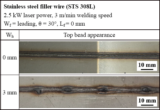
Bead appearance depending on the distance between wire tip to substrate
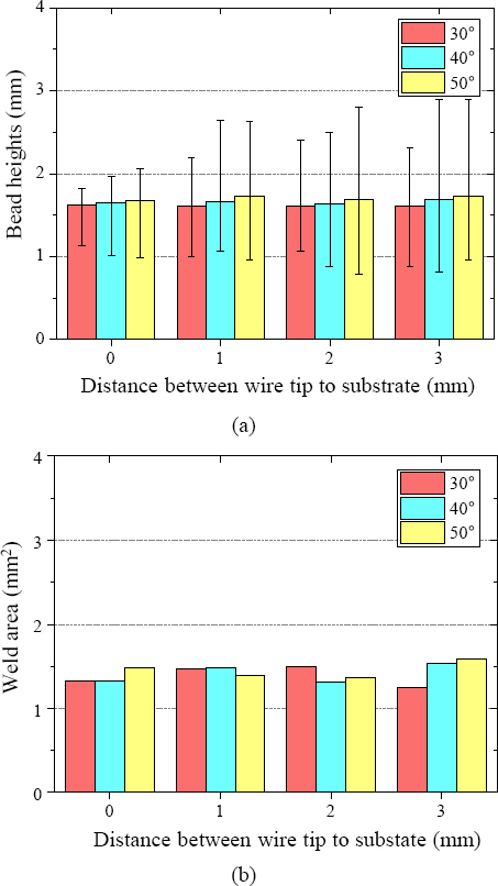
Analysis of (a) surface roughness and (b) weld area for the welds used stainless filler wire according to the Wh, θ
3.1.2 Al 5356 wire
Fig. 5 and 6 show the weld bead analysis results of the welds using Al filler wire. The wire fed from the leading direction could secure a more stable transfer than the trailing one, which is same tendency with a STS wire. In all cases, no crack was identified from bead appearance, but non-uniform beads were formed due to the semi-solid droplets attached to the substrate. When θ was fixed at 30° and Wh was increased from 0 to 3 mm, the average bead height increased by 0.04 to 0.08 mm. When θ was increased from 30° to 50° at 3 mm of Wh, the average bead surface height slightly decreased from 0.90 to 0.88 mm (Fig. 6a). Compared to the STS 308L wire, the weld area significantly increased even in same heat input conditions due to the low melting temperature of Al (Fig. 6b). When Wh increased from 0 to 3 mm, the weld area decreased from 2.88 to 1.84 mm2. Because droplet ejection and solidification disrupted the laser path, and caused energy transfer problems. The weld area reduction tendency at feeding angles of 40° and 50° was more significant than that at 30°. On the other hand, a uniform bead width of 2.4 to 2.45 mm was measured although the Lf was increased up to 10 mm, indicating that the interaction of Lf with other variables (e.g., θ and Wh ) was insignificant.
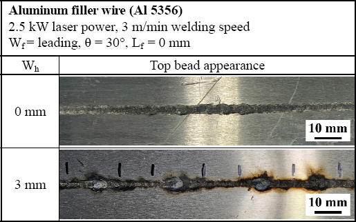
Bead appearance depending on the distance between wire tip to substrate
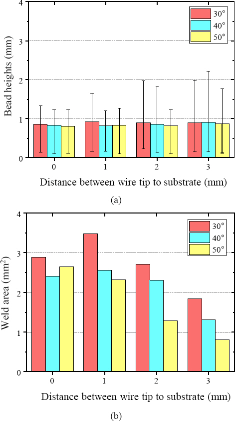
Analysis of (a) surface roughness and (b) weld area for the welds used aluminum filler wire according to the Wh and θ
3.2 Effects of welding variables on droplet transfer
For laser welding, the droplet size, surface tension on the droplet, and repulsive force against the laser beam are major forces that cause droplet transfer. Therefore, it is necessary to analyze the plasma/plume generation that can affect droplet size and the repulsive force during laser welding.
3.2.1 STS 308L wire
The STS wire has a higher density than Al, so the gravity affecting the droplet is stronger than Al. As the increase of Wh, bridge transfer mode changes into free-flight droplet transfer mode (Fig. 7a and 7b). When Wh was more than 2 mm, the droplets exhibited free-flight transfer, but no burnback phenomenon occurred due to the low thermal conductivity and high melting temperature characteristics of STS. The red area indicates the trajectory of the laser beam. In the case of STS, the trajectory of the laser beam constantly remained on the wire tip, and free-flight droplet transfer occurred regularly with an interval of 0.3 to 0.4 s.
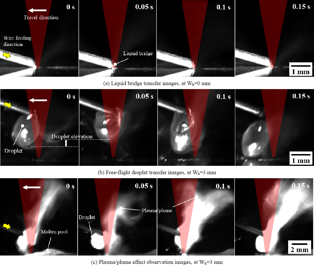
High-speed camera images captured during laser welding with stainless steel filler wire. (a) liquid bridge transfer, (b) free-flight droplet transfer, and (c) plasma/plume generation
The laser beam contacted the substrate on the right side of the droplet and generated a plasma/plume, where provided the force to push the droplet to the left side. In high-speed camera movies, fluctuations in droplet height were observed due to the internal flow and vibration. No oxides were observed floating on the droplet surface.
3.2.2 Al 5356 wire
When the Al wire was applied, bridge transfer was also observed at Wh = 0 mm (Fig. 8a). The most stable transfer was found under the bridge transfer condition. As the Wh increased, the transfer mode changed into free-flight droplet transfer. The wire tip was convex due to the influence of the laser power and the conductive heat of the molten pool. This is appears to be due to the high thermal expansion rate of the Al wire. The high thermal conductivity of the Al wire caused the burnback phenomenon, and the wire was suddenly shortened by 1.1 mm on average (Fig. 8b, time = 0.15 s). This means that the wire tip deviates from the laser trajectory, indicating that the energy transferred to the wire is supplied irregularly. Some droplets were not transferred despite of the droplet contact with the molten pool when Wh was large. This is because the Al oxide film with a high melting temperature was formed and the surface tension was reduced due to the low droplet temperature. The droplet transfer duration was irregular and highly dispersed, in 0.25 to 0.55 s range. In addition, the magnesium content in Al caused spatters even under the bridge transfer condition as shown in Fig. 8c.
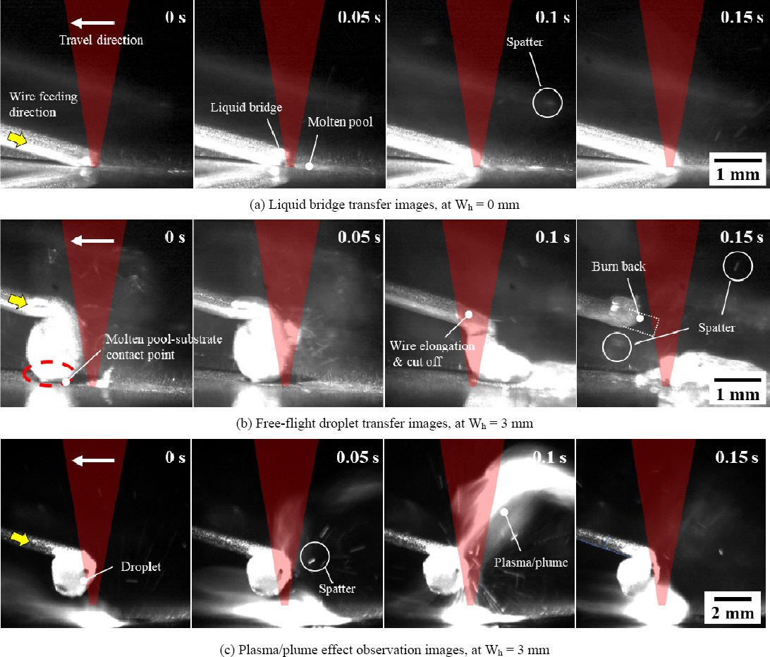
High-speed camera images captured during laser welding with aluminum filler wire. (a) liquid bridge transfer, (b) free-flight droplet transfer, and (c) plasma/plume generation
Since protective gas was supplied to prevent oxidation, less plasma/plume was generated compared to STS wire laser welding (Fig. 8c). The Al droplet also leaned to the left of the laser beam, because of the collaboration between the repulsive force of the plasma/plume formed onto the droplet and the surface tension between the Al wire and the droplet. The Al droplet hung to the left of the laser beam, because of the interaction between the repulsive force of the plasma/plume formed onto the droplet and the surface tension between the Al wire tip and the droplet.
4. Discussion
When the wire was supplied from a trailing direction, the bead height significantly varied regardless of the wire type. This indicates that stable droplet transfer is difficult under the application of the trailing method.
Among the selected variables, the distance between the wire tip and substrate (Wh) is judged to be the main factor that determines the transfer mode. As the distance increased, bridge transfer changed into free-flight droplet transfer because of changes in force balance between the laser induced repulsive force, gravity, and surface tension. In the case of bridge transfer, the sum of surface tension and gravity is larger than the force that separates the melting droplet from the wire, and the distance from the wire tip to the molten pool was close, resulting in stable transfer. As the Wh increases, surface tension interrupts separation from the wire because of cool droplet temperature. In particular, the burnback phenomenon frequently occurred under the application of the Al wire, but it did not occur when Wh was 0 mm. This indicates that process stability can be improved by constructing an environment where continuous energy transfer can be performed by bridge transfer.
The wire feeding angle (θ) acts as a factor that determines the contact area between the wire and the laser and the surface tension between the wire and the droplet. As the θ decreased, the area contacted by the laser beam increased and the contact area between the wire and the droplet decreased. It means that transfer can be promoted at relatively low angles, even if the droplet size is small. The change in the melting area depending on the θ was almost constant for the STS wire, but it significantly varied for the Al wire. Accordingly, the allowable range of the feeding angle should be determined based on the laser beam absorption rate of the selected wire.
On the other hand, the effect of the focal position (Lf) on transfer was insignificant. It is possible that the energy density within the selected parameters was not significantly reduced, or the beam diameter was not significantly expanded.
The recently launched wobble head can reduce sensitivity to laser-wire position adjustment by supplying the beam over a larger area than the wire diameter. Further research is required as it is expected to change droplet transfer, including the molten pool size.
5. Conclusions
In this study, laser wire welding was performed using aluminum and stainless wires, and variables that play a dominant role in droplet transfer were examined.
1) The wire feeding angle (θ) affects the contact area between the laser beam and the wire, and acts as a main factor that changes the energy transfer to the wire.
2) The distance between the wire tip and substrate (Wh) acts as a main factor that determines the droplet transfer mode. As the distance decreases, free-flight droplet transfer was altered to bridge transfer, and burnback occurrences were reduced. For that reason, it is recommended that the wire tip position be close enough to contact the molten pool surface.
3) Feeding the wire in the leading direction offers a relative advantage compared to the trailing direction in terms of energy transfer.
Acknowedgements
We would like to acknowledge the technical & financial from the MOTIE (Ministry of Trade, Industry, and Energy) in Korea (Grant: 20014809).