Aluminum Arc Welding Technology to Improve Quality and Productivity of Electric Vehicles
Article information

Abstract
In the automobile industry, the use of aluminum bodies is increasing to reduce to the weight of automobile owing to the recent carbon-neutral policy. Because of a significant competition in the electric vehicle market, the technologies for batteries and motors must be secured. In particular, the main parts of the battery are made of copper and aluminum materials, and the battery platform is also made of aluminum materials to reduce the weight. Despite the high demand for aluminum materials, aluminum arc welding is known to be a difficult process owing to pores and cracks. Therefore, this thesis aims to investigate the characteristics of welding of aluminum materials in general and arc welding technology applied to electric vehicles.
1. Introduction
The supply of environmentally friendly cars has been actively increasing recently in response to global warming and climate change. The most promising type of car to replace the current cars with internal combustion engine is electric vehicles (EVs) with rechargeable batteries. Furthermore, as the European Parliament has decided to ban the sale of cars with internal combustion engine in Europe after 2035, the development and production of EVs are emerging as a critical issue in the automobile industry. Unlike the conventional internal combustion engines consisting of engines and transmissions, EVs have motors and batteries at the core of the new powertrain, and new platforms for mounting and driving motors and batteries are being developed and applied. In particular, welding and bonding technology for copper and aluminum metals is essential because the main components of a battery include major electrodes, busbars, modules, and a case made of copper and aluminum materials1). Moreover, as various vehicle weight reduction strategies are required to compensate for the increase in battery weight, the chassis, which houses the battery and motor, requires a new lightweight platform design, and aluminum is currently in the spotlight as a representative material for chassis2). This technical thesis aims to summarize general information about aluminum welding from basic material properties to welding know-how that can be applied to the components of EVs including chassis and platforms.
2. Characteristics of aluminum welding materials
2.1 Characteristics of aluminum
Aluminum has the crystal structure of face centered cubic (FCC) lattice. Pure metal aluminum, which is highly reactive, exists as aluminum oxide (Al2O3) in nature. The aluminum oxides densely formed on the surface of aluminum can prevent corrosion. Thus, the high corrosion resistance of aluminum can prevent corrosion in seawater environment. As aluminum has high strength to specific gravity ratio and high malleability, it is easy to create various forms of products through processes such as cutting and pressing. Table 1 compares the physical properties of aluminum and iron.

Material properties of Al and Fe
2.2 Classification of aluminum alloys
Aluminum alloys are broadly categorized into wrought alloy and cast alloy. The types of aluminum alloys are classified by chemical components, and further classified by properties required by wrought and cast alloys3,4). Table 2 classifies aluminum alloys based on processing method, heat treatment type, and alloy components.

Classification of aluminum alloys
2.2.1 Wrought aluminum alloys
Wrought aluminum alloys are identified by four-digit numbers based on the standard established by the Aluminum Association. The first digit represents the principal alloy element, the second digit represents the modification of the alloy or impurity limits of pure aluminum, and the last two digits represent the types of alloys. Table 3 compares the national standard identifications of wrought aluminum alloys.

Wrought aluminum alloy reference chart
2.2.2 Cast aluminum alloys
Cast aluminum alloys are also identified by four-digit numbers. The first digit represents the principal alloy element, the next two digits represent the alloy purity or alloy type, and the last digit written after the decimal point represents the product type (0: casting, 1: ingot). Table 4 compares the national standard specifications for casting and die-casting aluminum alloys.

Comparison of aluminum casting alloy national standard specification
2.3 Characteristics of aluminum alloy elements
2.3.1 Role of aluminum alloy elements
The principal elements of aluminum alloy are Cu, Mn, Mg, Zn, and Si. Other elements such as Ni, Cr, Ti, Zr, and Sc are also added in trace amounts to obtain special properties.
Any other elements are residual elements that are impurities, which cause adverse effects on mechanical properties. Mg and Mn increase strength and improve work hardening through the solid solution strengthening effect. Cu causes precipitation hardening, increases strength, and reduces ductility, weldability, and corrosion resistance. Si increases ductility and strength, and causes precipitation hardening when combined with Mg5). Zn causes precipitation hardening and stress corrosion6).

3. Characteristics of welding aluminum alloy
3.1 Welding characteristics of aluminum alloys
There are certain characteristics of welding that require extra caution due to the inherent properties of aluminum alloys. The melting point of aluminum is 650°C, but since the melting point of the oxide film on the aluminum surface is 2050°C, the surface will not melt by straight polarity arc welding, resulting in melting defects. In addition, pores may occur due to high thermal conductivity, and for certain aluminum alloys, high-temperature cracks may occur depending on the welding rod7). Proper preparation before handling and welding aluminum is required to prevent such defects. Fig. 1 shows the work sequence for aluminum welding.

Work sequence of aluminum welding
3.2 Welding wire
3.2.1 Selecting welding wire
For aluminum welding, welding rod selection is important because it can help prevent cracks and achieve optimal strength of the weld. Ductility, high temperature behavior, creep strength, and other properties should be considered depending on the purpose. Generally, welding rods should be equal to or greater than the base metal in terms of mechanical properties, corrosion resistance, and components, but some aluminum alloys are welded with welding rods that do not match the base metal in order to give the welded part special properties. Table 6 shows an appropriate welding rod selection guide.

A guide to selecting an appropriate welding rod
3.2.2 Managing welding wire
Welding rods become contaminated with moisture, dust, and oil when exposed to the atmosphere for an extended period of time, which could cause welding defects. Therefore, they must be dried at 45°C or at least wrapped with vinyl to reduce the adverse effects. Welding rods can be easily damaged because aluminum is ductile and vulnerable to damage. Therefore, they should be stored so that aluminum would not affect the delivery of the welding rod. When stored together with steel welding rods, caution is required as they can deform due to differences in drying temperatures and other reasons. Once a welding rod is opened, it is preferable to use it within 6 months. It is possible for a wire to form condensation when being exposed to a warm and humid work site after being in cold storage. To prevent this, the wire feeding device should be heated.
3.3 Preparations for welding aluminum alloy
3.3.1 Storage and handling
Aluminum is susceptible to damage as it is ductile. Therefore, aluminum should be protected by covering it with soft materials such as wood or polyethylene blocks, or by using nylon ropes or leather straps, to prevent damage.
3.3.2 Cleaning and degreasing
Welding defects in aluminum can be prevented by removing contaminants on the oxide film and surface before welding. Organic solvents contain hydrogen and oxygen, which cause pores and suspended matters. Thus, they should be removed before welding to ensure good quality. Cleaning action occurs when variable polarity or reverse polarity arc welding is performed. Hence, high-quality welding can be achieved just by washing the solvent of the aluminum base metal8).
3.4 Welding defects of aluminum alloys
The inherent properties of aluminum materials may cause various defects may occur during welding. The most frequently occurring types of defects are pores and high-temperature cracks.
3.4.1 Process initiation
The main cause of pores in aluminum welding is hydrogen (H). Fig. 2 shows a graph of the hydrogen solubility of aluminum according to temperature. The hydrogen solubility of aluminum is very high in the liquid phase, but very low in the solid phase. As a result, dissolved hydrogen in molten aluminum is released as bubbles in amounts that exceed the solubility limit during the solidification process. Moreover, the quick cooling speed causes bubbles to become trapped inside the weld metal, ultimately resulting in pore defects. There are various causes of hydrogen generation in the weld zone, including the hydrogen content of the base metal or welding rod, hydroxides or contaminants on the surface, and the moisture in the shielding gas9). Therefore, in order to prevent pore defects, extra care should be made with the base metal, welding rod, and the surrounding environment.
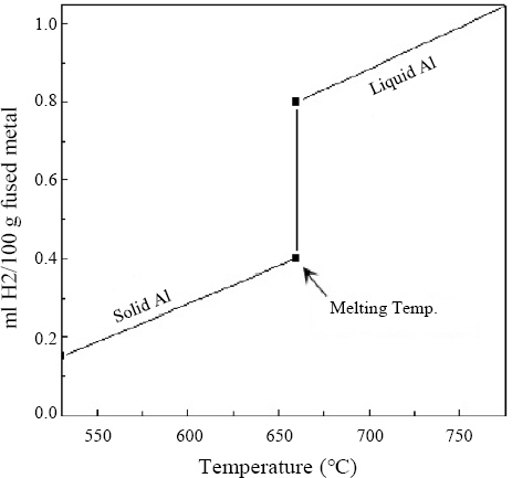
Hydrogen solubility in aluminum
3.4.2 Cracks
The types of cracks during aluminum welding typically occur at high temperatures in alloys, but not in pure metals. High-temperature cracks occur at temperatures above the solid phase line and can be categorized into theories such as solidification cracking, liquation cracking, and ductile degradation cracking. In the process of the molten metal solidifying, dendrites continue to grow and isolate the residual liquid with a low melting point. The isolated liquid cannot completely fill the gaps between the dendrites, causing cracks due to tensile stress generated after welding10). High-temperature cracks can be prevented by controlling the content and binding force of S and P of the base metal should be controlled, or through low-heat welding and proper bead shape.
4. Aluminum arc welding machines
4.1 Composition and management of welding machines
4.1.1 Welding torch
For MIG welding, a wire is supplied through a contact tip in the torch, and the current flows from the wire to the base metal through the contact with the contact tip. The torch must be light, strong, and easy to maintain to make it easier for the welder to handle. The diameter of the nozzle affects the flow rate of the shielding gas. The appropriate flow rate of the shielding gas should be selected cautiously as it affects the oxidation prevention of the weld zone, spatter, and pores. Fig. 3 shows the configuration of the MIG welding torch and parts.

Configuration of MIG torch
4.1.2 Wire feeder
A wire feeder consists of a wire reel and a feeder unit. There are three types of feeding: push, pull, and push- pull. The push type is used for large diameter welding rods, whereas the pull type is used for small diameter welding rods. The push-pull type is a system that combines drive rolls to both the inside of the torch and the wire reel feeder. It is suitable for using wires of ductile materials such as aluminum.
4.1.3 Wire drive roll
Aluminum wires are highly ductile and can deform easily under roll pressure, causing wire jams at the tip or feed line. Therefore, 4 drive rolls should be used rather than 2, to appropriately adjust the roll pressure. Fig. 4 shows the configuration of 4 drive rolls.
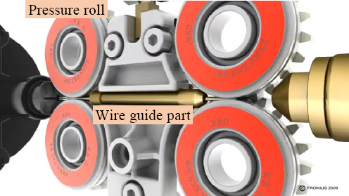
Configuration of wire drive roller
4.1.4 Contact tip
The contact tip is a component of the welding power circuit and has the purpose of providing current to the wire. It is made of copper or brass, and may have different lengths. A worn tip causes unstable contact with the wire, which causes arc instability and welding defects. Thus, it should be replaced at appropriate intervals.
4.1.5 Liner
Aluminum wires are made of a softer material than aluminum to be fed to the tip of the torch with minimum resistance. Teflon and graphite-based materials typically have excellent rigidity and friction, and the surface of the liner is smooth, resulting in low feeding resistance. Teflon has high expendability and graphite is sensitive to heat. Thus, the liner should be replaced at regular intervals as it is an expendable part.
4.1.6 Gas regulator
There are different types of gas regulators depending on the gas. A gas with suitable density should be used. When using CO2 gas, it is preferable to use a gas controller with a heater to prevent the gas from freezing due to the vaporization heat.
4.2 Types of welding machines
4.2.1 Tungsten Inert Gas (TIG)
TIG welding is performed using tungsten electrode rods and inert shielding gases without consume any electrodes. It is characterized by a constant current, which means that the current does not change even if the arc length is changed. It can have AC and DC power sources depending on the characteristics of current and is classified as DCEN or DCEP depending on the polarity of the electrodes.
4.2.2 Metal Inert Gas (MIG)
MIG welding is a type of gas metal arc welding (GMAW) process that uses inert shielding gases (Ar, He), in which an arc occurs between the welding rod and the base metal by applying a current through the welding rod while feeding it at a constant speed. The droplet transfer phenomenon varies depending on the type of gas, current, and voltage used, and affects the welding quality. Fundamentally, it has constant voltage characteristics, and can be categorized by the power control method.
4.2.3 Pulse MIG
Pulse MIG welding has intermediate properties between spray transfer and short circuit transfer, which are transfer methods used in conventional MIG welding. The wire is melted at the base current to increase the volume, and an electromagnetic pinch force acts on the volume at the peak current, which transfers the volume from the tip of the wire. The ranges of current and voltage can be expanded, and appropriate current and voltage can be selected depending on the diameter and material of the wire. Furthermore, the input heat of the base metal can be controlled to maintain good joint performance.
4.2.4 Inverter welding machine
A conventional thyristor welding machine controls the phase using the gate signal from the gate terminal, whereas the inverter welding machine can control the current output more quickly and accurately as it controls the energization time of the power transistor. The development of inverter welding machines has significantly improved workability because it reduced the weight of the conventional welding machines by up to several hundred kilograms. In addition, as alternating current welding and pulse welding have become possible to use, the welding quality can be enhanced by controlling the of the amount of penetration and heat input, thereby improving welding quality11).
5. Aluminum welding conditions and quality assurance
5.1 Main conditions for welding
5.1.1 Welding speed
Welding speed is a variable that affects the bead shape and penetration. Excessive welding speed results in narrow bead width and shallow penetration due to a lack of heat input. In contrast, insufficient welding speed results in larger weld zone or heat-affected zone due to a higher amount of melting wire and high heat input12).
5.1.2 Current
In GMAW, current is an important variable that determines welding speed and penetration as well as the volume transfer mode13). Since the current is proportional to the wire feed rate, GMA welding controls the welding current by adjusting the wire feed rate. An appropriate wire feed rate should be selected as excessive welding current forms convex beads, resulting in poor appearance. In general, when the current is increased, the voltage must also be increased to prevent a short circuit and obtain good welding quality.
5.1.3 Voltage
The welding voltage is proportional to the arc length and acts as an important variable in deciding the bead shape and volume transfer mode. When voltage is increased, the bead height decreases while the bead width widens, resulting in a flat bead shape. The penetration increases to a certain point before it decreases.
5.1.4 Contact tip to work distance
The contact tip to work distance (CTWD) refers to the length from the front end of the contact tip to the front end of the wire electrode. As CTWD increases, the sealing effect of the weld zone of the shielding gas and the current output of the arc decrease, making the arc unstable due to a short circuit, resulting in defects such as pores. Conversely, if the CTWD is too short, it is easier for spatter to become attached to the nozzle, which deteriorates appearance as well as workability of the weld zone.
5.1.5 Shielding gas
The shielding gas serves to protect the weld zone from being oxidized by the atmosphere. In aluminum welding, inert gases such as argon, helium, and argon-helium mixed gases, which have differing characteristics, are most commonly used14). Inert gases such as helium, neon, argon, krypton, xenon, and radon do not chemically bond with other elements at any pressure or temperature. Inexpensive argon is widely used as a shielding gas for welding. It has a larger cleaning effect and much more stable arc start than helium.
5.2 Welding process for quality assurance
5.2.1 Start and end of welding
Aluminum is highly susceptible to fusion defects at the start of welding due to its high thermal conductivity and low density. In order to prevent fusion defects, a high welding current is applied at the start of welding so that the base metal starts to melt as soon as the arc is ignited. Afterwards, the welding current decreases when a sufficient amount of heat is injected into the molten pool, and the crater current also decreases to prevent crater cracks at the welding end zone11). Fig. 5 shows the current waveform control during welding.
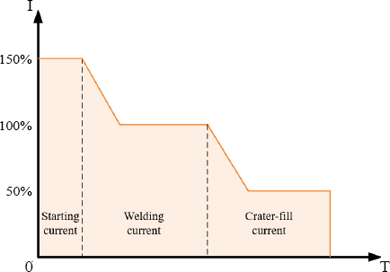
Current waveform at the start and end of welding
5.2.2 Spatter Free Ignition (SFI)
In conventional welding machines, an arc is ignited after a short circuit occurs. The current rises to around 700A to cause a short circuit during the short circuit process. As soon as the short circuit occurs, an explosive arc is generated by the high current, and large amounts of spatter are generated. Such spatters may affect the quality of the weld zone and may shorten the lifespan of the contact tip. The Spatter Free Ignition (SFI) technology can be a solution to this problem. The moment the wire makes contact with the base metal, a welding current is applied and the wire reverses, resulting in arc ignition without any spatter. Then, when the arc length reaches a certain level, the wire is fed at a constant feed rate. As a result, the lifespan of the contact tip is improved and even a wire with a thick diameter can stably initiate an arc11). Fig. 6 shows a comparison between conventional arc ignition and SFI arc ignition .
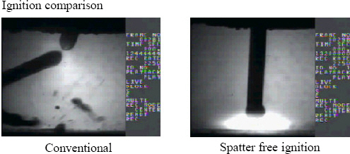
Comparison of conventional arc ignition and SFI
5.2.3 Synchro Pulse
The most important feature of synchro pulse is welding by synchronizing the pulse current and the wire feed rate. Fig. 7 illustrates pulse welding by synchronizing the average welding current and the wire feed rate with a synchro pulse. When wires are fed at a high feed rate, the generated pulse arc has a high average current. In contrast, at a low feed rate, a low average current pulse arc is generated, minimizing heat input to the base metal and forming a wavy bead. In addition, electromagnetic welding is possible due to a low heat input, and the number of pores can be reduced because the amount of hydrogen generated in the base metal around the weld metal is reduced.
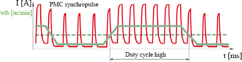
Waveform during synchropulse
5.2.4 Cycle step
Cycle Step is a program capable of minimizing welding heat input by precisely controlling the short-circuit time and arc time by reversing the wire. As a result, it is possible to form a clear wave pattern welding bead and minimize the heat-affected zone. The contact between the wire and the base metal initiates a short circuit, performing the welding, and then short circuit is resolved through the reverse of the wire and arc re-ignites simultaneously. Accurate volume transfer can be designed through periodic and precise control of such sequence. In particular, it is useful for gap welding because the amount of heat input can be controlled. Moreover, it is also useful for welding aluminum and iron heterogeneous brazing, or galvanized steel sheets15).
Fig. 8 shows the characteristics of Cycle Step.
Characteristic of cycle step
5.3 Welding distortion prevention technology
The weld metal reaches the maximum expansion at the time of solidification, and shrinks with cooling. However, shrinkage is suppressed by the nearby base metal, resulting in tensile stress in the weld. Deformation occurs when this stress exceeds the yield strength.
During welding, the base metal around the weld metal is also heated to the melting point. At the end of welding, the base metal cools and begins to shrink with the weld metal. At this point, internal stress is applied if it is prevented from shrinking naturally.
5.3.1 Minimizing deposited metal
Contractile force increases with higher amounts deposited metal. In fillet welding, the strength determines the effective neck thickness, meaning if an excessively convex bead is formed, the actual allowable strength does not increase but only the shrinkage force increases, which is why it is best to form an appropriate bead shape.
5.3.2 Reverse transformation
Reverse transformation is a method of setting the base metal before welding in the opposite direction to the transformation so that the contractile force after welding pulls the base metal to its original position.
5.3.3 Removing contractile force with reverse transformation peening
Peening is a mechanical method that applies force on the weld zone to decrease any residual stress. However, peening is not appropriate for a root pass bead as cracks occur and end up becoming hidden.
5.3.4 Reduction of welding duration
During welding, heating and cooling occur in complex cycles. Because it takes time for heat to transfer, the temporal factor affects deformation. In general, it is preferable to quickly finish welding before the base metal around the weld zone expands due to the welding heat.
5.3.5 Thermal contraction correction methods
The thermal contraction correction method reduces or eliminates deformation by heating the weld metal after welding with a gas torch to cause the metal to transform in the required direction. It is necessary to determine the amount of required heat, and although high temperature is not required, a large torch is still necessary to create a uniform and steep temperature gradient.
5.3.6 Reverse transformation calibration with hydraulic pressure
Due to the nature of the material, aluminum cannot be treated with heat. Moreover, thermal contraction methods are ineffective because it has high thermal conductivity. Therefore, a hydraulic calibration method is used to correct deformation with a press or calibrator to apply enough compressive stress that equals the yield stress.
5.4 Methods of minimizing welding defects
5.4.1 Shielding gas
In aluminum welding, the shielding gas typically consists of a mixture of inert gases such as argon and helium. Stable volume transfer is achievable with 100% argon gas but the penetration is lower than that of argon-helium mixed gas, and it is also more likely to generate pores due to hydrogen diffusion. 100% helium gas increases heat input, penetration, and arc stability, but the cleaning effect of the oxide film is lower than that of argon. Such properties vary depending on the mixing ratio of the gases, and with higher helium mixing ratio, a higher arc voltage is required for the arc ignition. Recently, a small amount of oxygen or nitrogen mixed gas is being used to increase arc stability14). Table 7 shows the characteristics of argon-helium mixed gas as helium mixing ratio increases.

Characteristics as the helium mixing ratio increases in argon-helium mixed gas
5.4.2 Cleanliness of the weld zone
The cleanliness of the weld zone should be managed during aluminum welding because it is critically related to pore defects. Aluminum welding should be carried out in a workspace separated from the tools and workspace used for steel welding. Moreover, it is preferable to remove any foreign materials and oil on the weld zone with acetone or a stainless-steel brush.
5.4.3 Preheating
If it is difficult to achieve sufficient penetration due to the high thermal conductivity of aluminum, a preheating process would be required before welding. It is preferable to not make the oxide layer too thick from excessive duration of preheating or excessive O2. In addition, special attention should be paid to the effect of the preheating temperature and time on the properties of the material, and particularly to the cold wrought alloys and quench aging alloys that have high Mg content.
5.4.4 Weld zone shape
During aluminum welding, the viscosity and surface tension of the molten region are very low, making it very difficult to obtain full penetration without backing. Thus, deterioration of fatigue performance is inevitable in the case of partial penetration. An alternative method is to design a welding joint with a double butt joint16). Double butt joints make it easier to work in the field with the alignment of the upper and lower surfaces, and exhibits excellent fatigue performance compared to the partial penetration weld zone. It can be a more reasonable alternative in actual work sites where it is difficult to create a full penetration shape without backing in a typical butt joint. Fig. 9 compares the shapes of the butt joint and the double butt joint.
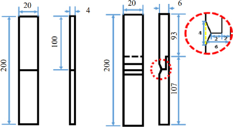
Aluminum butt joint specimen dimension. left side: butt joint, Right side: double butt joint
6.1 Application of aluminum in EVs
Chassis manufacturing methods using various lightweight materials are being researched and applied to satisfy the need for weight reduction due to the large weight of EV batteries. Although the existing steel- based chassis parts are also being replaced with lightweight materials such as aluminum, the application of aluminum body parts is stagnant due to factors such as chassis production process and cost increases. Unlike the upper chassis, aluminum-based lower chassis frames, which house the batteries and motors, are becoming the norm. As a result, arc welding is being applied to various types of aluminum plates and aluminum extruded panels, which form various electric car platforms. Although aluminum is also applied to battery cell and module manufacturing, laser welding is more generally applied compared to arc welding due to the thickness of the welding-bonding material. Fig. 10 is an example of the battery system of the underbody platform of an electric vehicle. It is an E-GMP platform that Hyundai- Kia Motors is applying to a platform dedicated to electric vehicles. Each battery module is rigidly connected to an aluminum structure called a lower cover or battery case. This structure protects the battery from collisions that may occur under normal driving conditions. In particular, in preparation for a side collision of the vehicle body, the grid structure of the battery case is designed to be firmly connected to the vehicle body. Various aluminum arc welding including hardware parts welding is being applied.
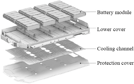
Battery system structure of electric vehicle (E- GMP, Hyundai-Kia Motor Company)
6.2 Low-power aluminum arc welding
The recently developed aluminum arc welding system uses digital control for efficiency optimization and can reduce power consumption by more than 25% compared to the conventional aluminum arc welding machines. Although the reduction in power consumption alone can reduce electricity bills and costs, it also has the advantage of being an effective response to green regulations in a sustainable society. A representative example of a sustainable green regulation is the mandatory greenhouse gas reduction with carbon emission rights. Such low-power aluminum arc welders can reduce carbon gas emissions by about 500g because they consume about 1kWh less power. This means that greenhouse gas emission can be reduced and promote sustainable production even when manufacturing a product with aluminum arc welding.
7. Conclusion
The basics of arc welding technology were reviewed for aluminum materials applicable to EVs that will replace internal combustion engines in the future. Alu- minum is a lightweight material, but special caution is required when it comes to arc welding because of low melting point and fast heat transfer. Fortunately, welding quality can be ensured using various arc welding control methods that have been developed. Effective application of solutions to aluminum parts in EVs using such technology is expected.