Evaluating the Welding Pulses of Various Tool Profiles in Single-Pass Friction Stir Welding of 6082-T6 Aluminium Alloy
Article information

Abstract
Aluminium alloy 6082-T6 plays a vital role in the fabrication of lightweight structures, especially for the manufacturing of artillery, defense vehicles, and aircraft. Aluminium alloy 6082-T6 is a well-known structural alloy having a high strength-to-weight ratio and favorable corrosion resistance properties in extreme environments. In this study, three friction stir welding (FSW) process parameters (spindle speed, weld speed, and shoulder penetration), two geometrical tool parameters to precisely describe the pin profile, and the shoulder profile were considered at five levels. Optimization was conducted using the Taguchi experimental design method, and FSW experiments were conducted in a conventional milling machine. The parameters were optimized to maximize the tensile strength for various plate thicknesses. The number of tool pin polygon edges determines the corresponding welding pulses. The results show that 105-110 pulses/s is an optimal value to achieve a high-quality, defect-free weld.
1. Introduction
Friction stir welding is a solid-state welding process; this remarkable up-gradation of friction welding was invented in 1991 by The Welding Institute UK1). Fig. 1 shows the graphical representation of the Friction Stir Welding Process. The process begins with securing the plates to be welded to a backing plate so that the plates do not move apart during the welding process. A rotating, wear-resistant tool is plunged on the interface between the plates and moved forward along the rolling direction of the plates to form the weld. This tool has a probe and shoulder which stirs the material to be joined and forges the surface. FSW comes together with forging and extrusion processes. The probe and shoulder extrude the material by mixing, and the shoulder alone forges the material surface to be joined, by the axial force given through the shoulder plunging.
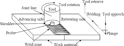
Graphical representation of friction stir welding
Friction Stir Welding facilitates welding of the plate to plate joints for several applications. This process is chosen for the welding of AA 6082-T6 (Al-Mg-Si alloy) of various thicknesses. This alloy finds use in structural and other industrial applications. FSW process is exceptionally well suited for butt and lap joints in aluminium. Production of aluminium alloy components is not very complicated, but the joining of these materials can sometimes cause serious problems2). The lack of structural transformations, excellent thermal and electrical conductivity cause problems in fusion and resistance welding of aluminium alloys3-5). These lead to welding of aluminium alloy by friction stir welding. Since aluminium is difficult to weld by arc processes, but it is very simple to weld by Friction Stir Welding.
Moreover, the tool geometry and interaction of tool with base metal is essential for attaining good quality of welds, different tool geometries were designed and manufactured6-9). The mechanism of bonding involves efficient movement of plasticised material around tool profile, so the joints were investigated thoroughly for defects under varying conditions of process parameters. However, the conventional milling machine offers the tool rotational speed, and welding speed by their spindle speed and table feed, only the axial force is not easy to attain. This axial force parameter can be accomplished by tool shoulder penetration10,11). The axial force get increases while the tool shoulder penetration increases. Even in FSW machine axial force is challenging to retain through-out the welding.
Nevertheless, the shoulder penetration/plunge depth has been maintained12). In this study, three important process parameters such as spindle speed, welding speed and shoulder penetration; and two tool geometries shoulder profile and pin profile were considered13). Many research works were considered a single plate thickness of around 5 mm and reported the process parameters influence in Friction Stir Welding of Aluminium alloys.
In this experiment, the different plate thicknesses of 4 mm, 6 mm and 8 mm were taken, and the friction stir welding was carried out to optimise the parameters by the Taguchi experimental design technique11). In FSW, the tool pin diameter is constrained to the thickness of the plate. The same diameter of the probe could not perform welding of all thicknesses14). Hence the parameters are optimised individually to each plate thickness. Then the effect of tool pin polygonal profile on joint strength was obtained from the optimised parameters. Finally, the optimum welding pulse to achieve a defect-free good weld was presented.
2. Experimental procedure
A conventional vertical milling machine with a capacity of 7.5 hp and 1800 rpm is used to carry out the experiments10,11). Spindle speed, welding speed, shoulder penetration; probe profile and the shoulder profile were considered as process parameters. After several trials, the range of process parameters such as spindle speed and welding speed15) were taken from 700 rpm to 1500 rpm and 0.8 mm/sec to 4 mm/sec respectively. Shoulder penetration was gradually increased in five steps from 0 mm to 0.16 mm and 0.20 mm respectively for 4 mm and higher thickness plates.
Non-consumable tools made of high-speed steel (HSS) were used to fabricate the joint. Five pin profiles namely square, pentagon, hexagon, heptagon and octagon were considered for 6 mm and 8 mm thick plates. The triangle pin profile was assessed for 4 mm thick plate along with other successive four profiles. Friction stir tool of the pin profiles, as mentioned above, was shown in Fig. 2. Each pin profile has five different shoulder angles in concave and convex shapes of -5°, -10°, 0°, +5° and +10°. These 5 × 5 combinations of friction stir tools were used for conducting experiments. Friction stir tool has shoulder and pin for frictional heat generation and stirring respectively. In this study shoulder diameter of 12, 18 and 24 mm and a pin diameter of 4 mm, 6 mm and 8 mm was used respectively for 4 mm, 6 mm and 8 mm plate thicknesses16-19). Table 1 shows the process parameters in detail.
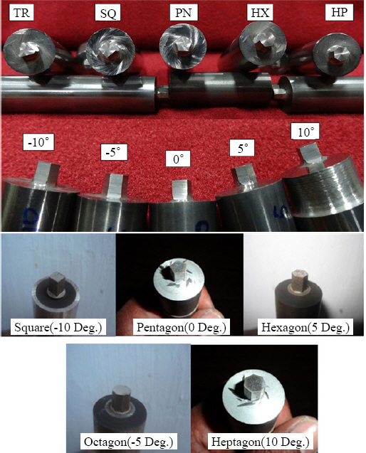
Various tool profiles
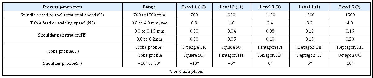
Process parameter with their range and values at five levels
The upper limits and the lower limit of the process parameters were found by conducting trial runs, by changing one of the parameters and keeping the remaining parameters at constant values. Feasible limits of these parameters were chosen in such a way that the joint should be free from visible defects. The intermediate levels were calculated from the following relationship.
Xi = 2 [2X - (Xmax +Xmin)] / (Xmax - Xmin)]
Where Xi is the required level value of a variable X; and X is any value of the variable from Xmin to Xmax. Xmin is the lower bound of the variable, and Xmax is the upper bound of the variable. The selected process parameters with their limits, units and notations are given in Table 1.
The 6xxx series aluminium alloys are well known and specifically high strength alloys with AL-Mg-Si constituents. Aluminium alloy 6082 has high strength and excellent corrosion resistance property among the 6000 series alloys. Alloy 6082 is hugely preferred in structural purposes, also termed as a structural alloy. The toting of manganese controls the grain structure, which in turn results in a stronger alloy. Chemical composition and mechanical properties of AA6082 were shown in Table 2.
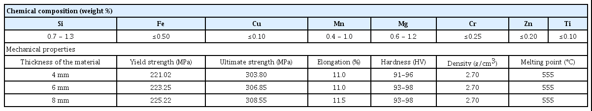
Chemical composition and mechanical properties of the 6082 alloy
Taguchi Experimental Design Technique20,21) assesses the influence of factors on the response. The means and the signal-to-noise ratios (S/N) for each control factors are to be calculated. Signals are indicators of effect on the average response, and noises are the measure of deviations from experiment output. The appropriate quality characteristic must be chosen using previous knowledge, expertise and understanding of the process22). In this study, the quality aspect ‘larger-the-better’ was selected according to correction, to maximise the response. In Taguchi Method, S/N ratio (ηj) in the jth experiment can be expressed as:
ηj = -10 log [1/n ∑ (1/Yijk2)]
Where ‘n’ is the number of tests and ‘Y’ is an experimental value of ‘i’th quality characteristics in ‘j’th experiment at ‘k’th test. In the present work, Tensile Strength (TS) data are analysed to determine the effect of FSW process parameters. Experimental results are transformed into a means and S/N ratio.
Welded plates were cut across the thickness of the mid welded portion, and specimens of size 40 mm x 10 mm was taken for metallographic examinations. As per standard metallographic procedure, the test specimens were prepared from the welded plates, and macro etched using Keller’s solution23). The metallographic study was carried out on weld nugget across the cross-sections of friction stir welded specimens using a scanning electron microscope (SEM).
3. Results and discussion
Aluminium 6082 Alloy has cut to dimension 200 mm × 76 mm × 4, 6, 8 mm. Square butt joint configuration was prepared to fabricate FSW joints with the non-consumable HSS tool. The friction stir welding was performed on the CM machine as per the L25 orthogonal array, as shown in Table 3. Taguchi’s orthogonal array was used to design experiments with five factors at five levels. The material was welded according to the specification of welding parameters. The Welded specimens were fabricated as per ASTM-E8 standards to evaluate the tensile strength of the joints24). The tensile strength of the FSW joints was assessed by conducting tests in TUE-CN-1000 Universal Testing Machine.
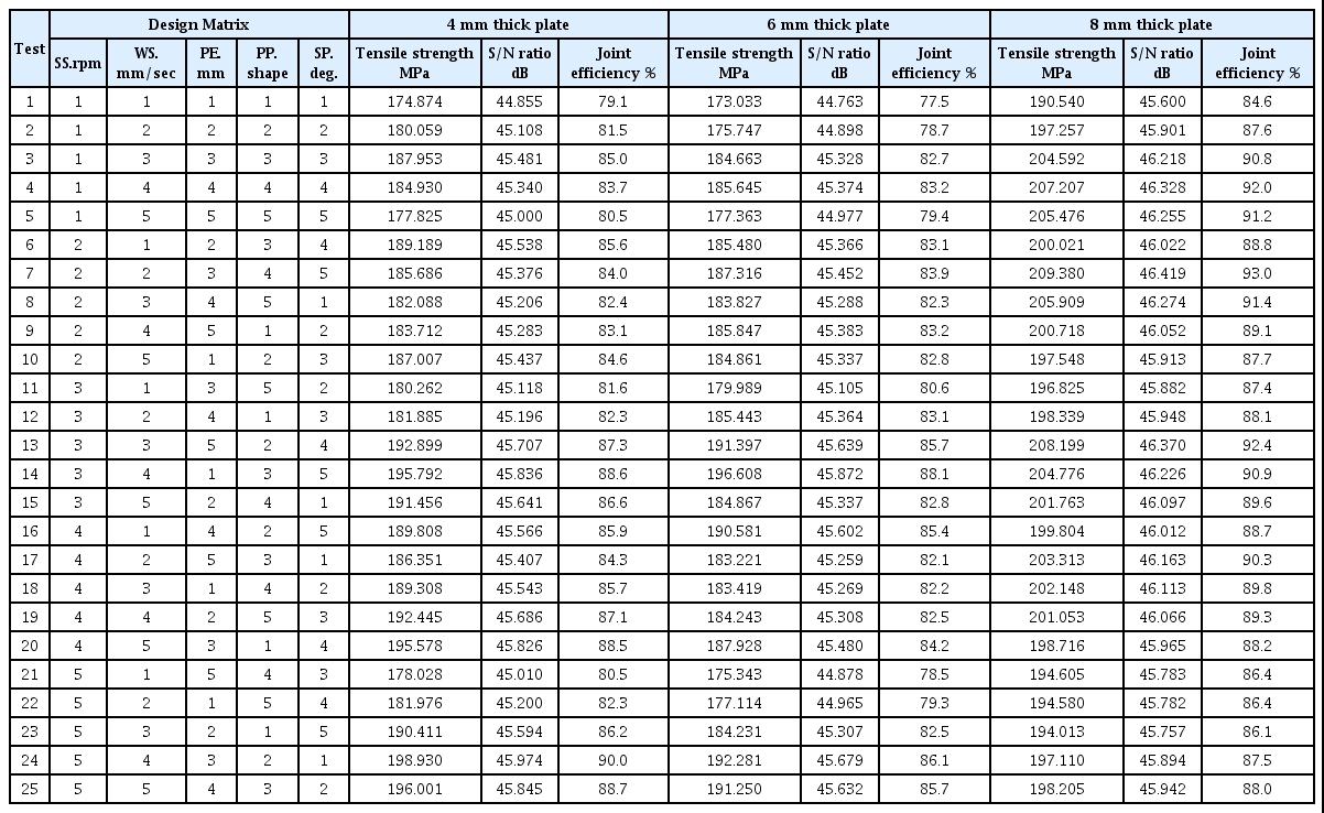
Design table and experimental value of tensile strength
During tensile testing, most of the specimens were broken at the retreating side of the heat-affected zone, as shown in Fig. 3. The tensile strength (TS) in terms of means and S/N ratios was established in Table 3. The results from the tensile tests were given as input to the Minitab software for getting optimised parameter levels to achieve a maximum tensile strength of the friction stir welded joints.
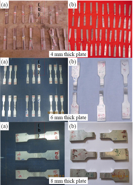
(a) Specimen before tensile test and (b) Specimen after tensile test
Analysis of the mean for each of the experiments gives a better combination of parameter levels. The mean response refers to the average value of performance characteristics for each parameter at different levels. Mean for one level is calculated as the average of all responses that are obtained within that level. The mean response of raw data and S/N ratio of TS for each parameter at levels 1, 2, 3, 4 and 5 were calculated and are presented in Table 4. Analysing means and S/N ratio of various process parameters it was observed that the larger S/N ratio corresponds to better quality charac- teristics. Therefore, the optimal level of process parameters is at the level of the highest S/N ratio. Fig. 4 shows that the Mean effect and S/N ratio calculated by statistical software, which indicates that the TS was maximum while using the maximum parameter level.
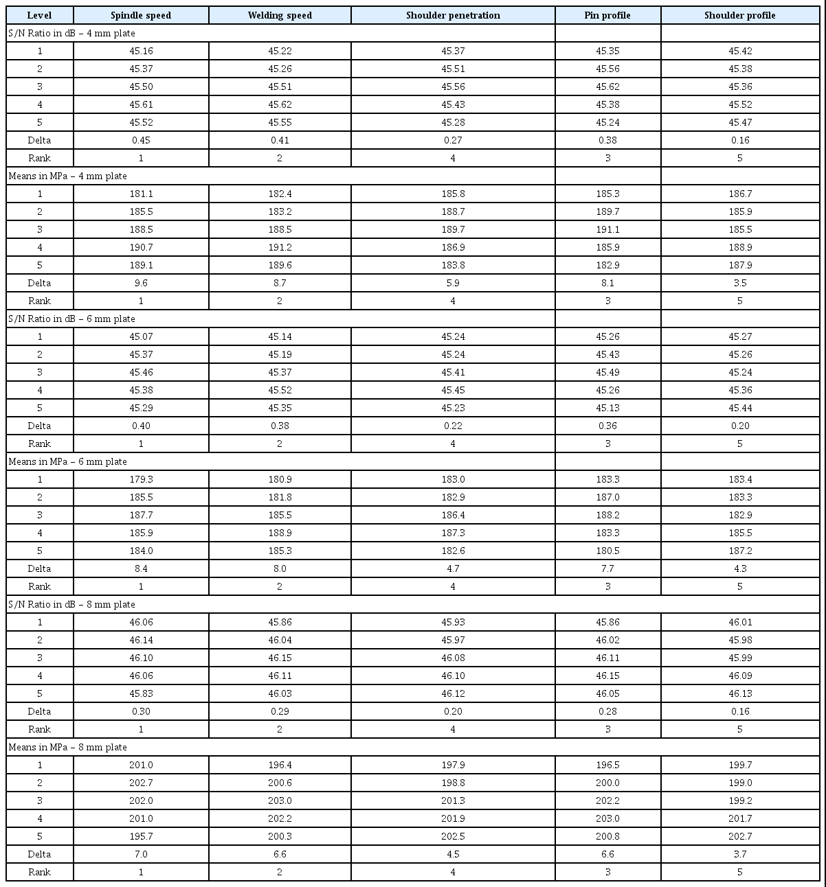
Response table for S/N ratio and mean
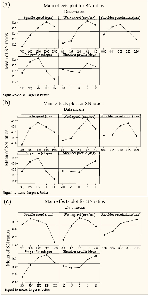
Parameter effect charts - S/N ratio (a) 4 mm thick plate (b) 6 mm thick plate and (c) 8 mm thick plate
Also, the response table ranking, given in Table 4, interprets the degree of the parameter which influences the response. The first dominant parameter is spindle speed which is followed by welding speed, pin profile, shoulder penetration and shoulder profile. Optimum process parameter levels for 4 mm thickness welded plate which is found to achieve greater tensile strength are 1300 rpm spindle speed; 3.2 mm/sec weld speed; pentagonal pin profile; 0.08 mm shoulder penetration; and 5° convex shoulder taper. For 6 mm thickness welded plate which is found to achieve greater tensile strength are 1100 rpm spindle speed; 3.2 mm/sec weld speed; hexagonal pin profile; 0.15 mm shoulder penetration; and 10° convex shoulder taper. For 8 mm thickness welded plate which is found to achieve greater tensile strength is such as 900 rpm spindle speed; 2.4 mm/sec weld speed; heptagonal pin profile; 0.20 mm shoulder penetration; and 10° convex shoulder taper.
The tensile strength of the joint is a function of spindle speed, welding speed, shoulder penetration, pin profile, shoulder profile and it can be expressed as
Tensile Strength (TS) = f (SS, WS, PE, PP, SP)
Tensile Strength (TS) = SSi’max + WSi’max + PEi’max + PPi’max + SPi’max - 4T
Where,
“i” indicates the levels, which varies from 1 to 5
T - Overall mean of the experimental values
The established linear equation predicts the maximum value of tensile strength at optimum process parameter levels is given by
TS4 mm = SS4 + WS4 + PP3 + PE3 + SP4 - 4T
TS4 mm = 190.7 + 191.2 + 191.1 + 189.7 + 188.9 - (4 × 186.978) = 203.69 MPa
TS6 mm = SS3 + WS4 + PP3 + PE4 + SP5 - 4T
TS6 mm = 187.7 + 188.9 + 187.3 + 188.2 + 187.2 - (4 × 184.468) = 201.43 MPa
TS8 mm = SS2 + WS3 + PP4 + PE5 + SP5 - 4T
TS8 mm = 202.7 + 203.0 + 203.0 + 202.5 + 202.7 - (4 × 200.484) = 211.96 MPa
Analysis of variance (ANOVA) for means has been carried out to identify statistically significant process parameters, which affect TS of FSW joints as shown in Table 5. Results of ANOVA indicate that the chosen process parameters are highly significant factors affecting TS of FSW joints. Effects of interaction between process parameters are not significant. Confirmatory experiments are carried out at obtained optimum level setting of process parameters. The tensile strength of FS Welded aluminium alloy 6082 T6 is found to be 198.23 MPa, 196.18 MPa and 204.74 MPa for the plate thicknesses of 4 mm, 6 mm and 8 mm respectively. This occurs within the poise interval of predicted optimal tensile strength.
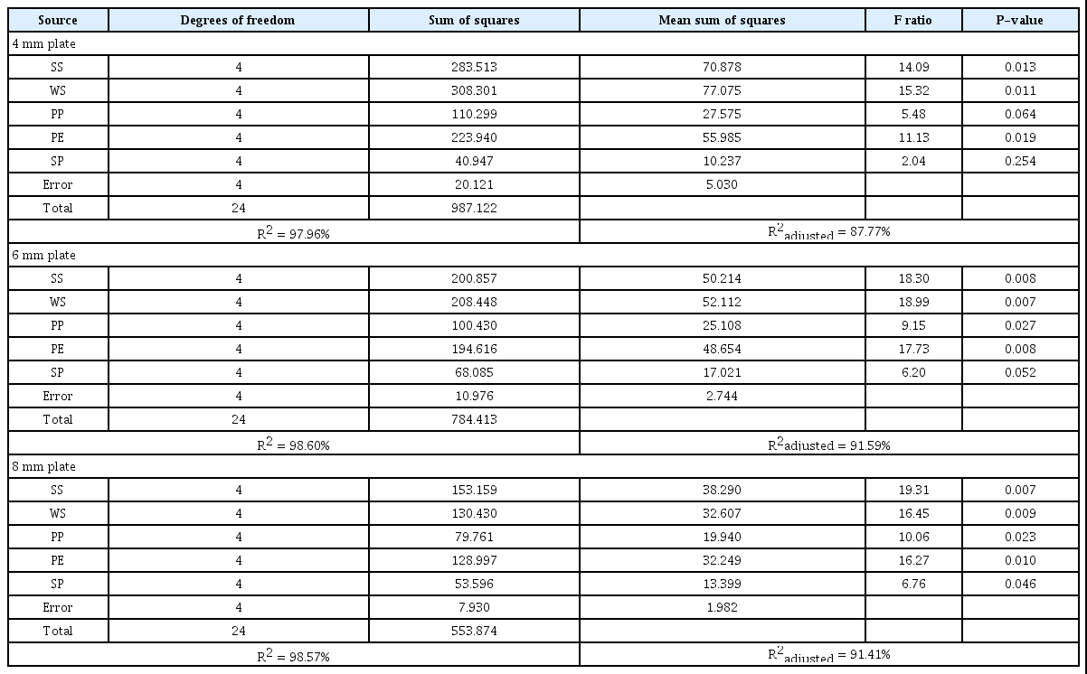
ANOVA for tensile strength (means)
The friction stir welded plates of different thicknesses specified in Table 6 show the different optimum values. The various tool size is the main reason for different optimum values. The tool size, mainly the probe size, i.e. diameter and probe length, is constrained with the plate thickness. The above data has been selected by considering the tool stiffness and tool life.

Optimal parameters for maximum tensile strength - different plate thicknesses
3.1 Metallographic Structure
The metallographic structure of the parent metal consists of elongated grain morphology with an average grain size of 9 μm. In FSW, the weld nugget zone experiences high strain and is prone to recrystallisation. Weld nugget has a recrystallised microstructure that consists of excellent intensively stirred harmonised grains25,26). The grain size of the weld nugget is decreasing with the increase of the number of polygon face edges.
Fig. 5 shows the metallographic structure of friction stir welded 4 mm, 6 mm and 8 mm thickness plates at various pin profiles. The microstructure of the weld nugget at the Optimum pin profile shows very fine and harmonised grains in all thicknesses. The grain size at weld nugget of 4 mm, 6 mm and 8 mm plates are ranging between 3 μm to 4 μm, 4 μm to 6 μm and 5 μm to 8 μm respectively.
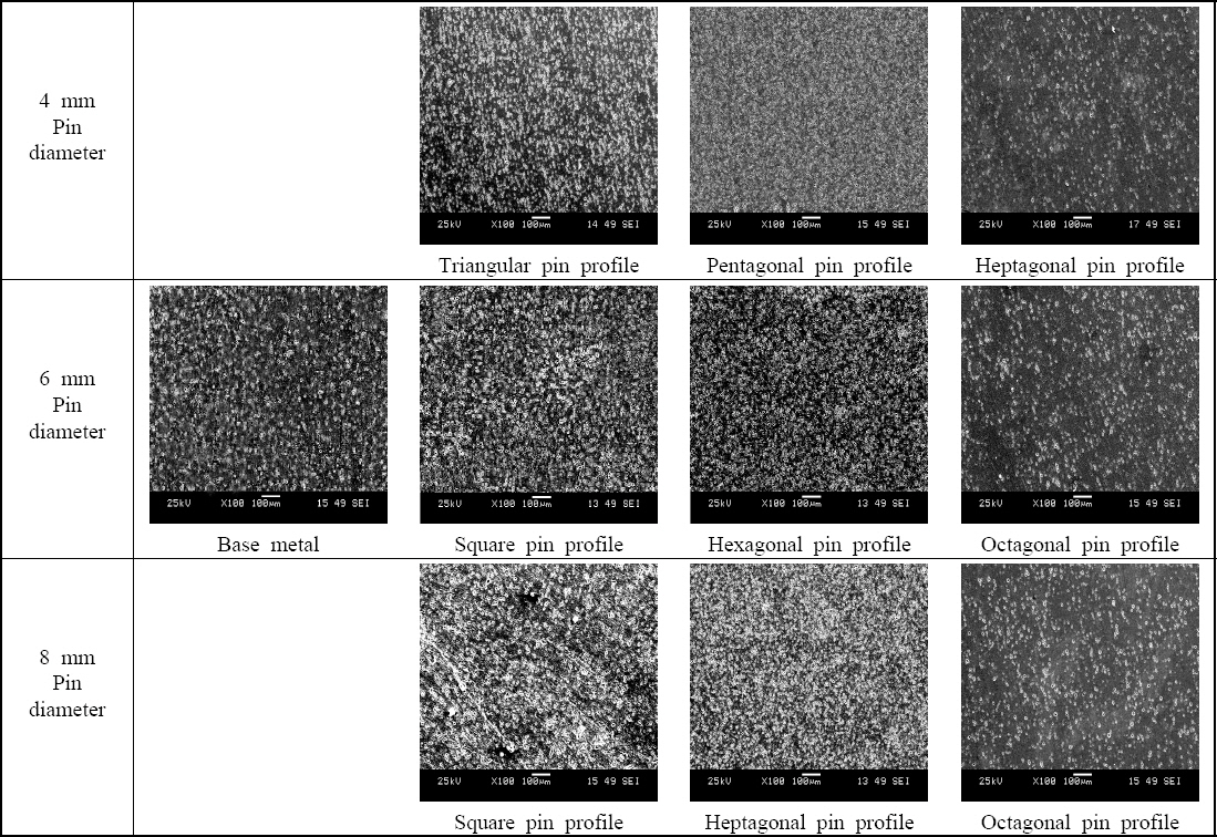
Microstructure of friction stir welded specimens at various pin profile and pin sizes of the tool
The microstructure of the weld nugget at the high number of polygon pin face edges shows refined grains in all thicknesses comparatively. However, the grain size ranges between 3 μm to 6 μm, 3 μm to 8 μm and 4 μm to 9 μm for 4 mm, 6 mm and 8 mm plates respectively. Higher polygon pin face edges approach circular pin, and this vanishes the pulse formation in stirring. This pulse formation leads to distortion of grains, due to the decreases in the dynamic area or lack of sweeping between the tool and the material. Whereas a low number of polygon pin face edges generates high dynamic area, and this shows the coarse grains relatively. The grain size ranges between 5 μm to 7 μm, 6 μm to 8 μm and 7 μm to 9 μm for 4 mm, 6 mm and 8 mm plates respectively.
3.2 Effects of Tool Pin Profile and Pulses
The pin profile varies with different thickness of the plate to be welded. Fig. 6 shows a different shape of the tool that gives a defect-free good weld to the respective plate thicknesses. The tool pin profile with flat faces produces a pulsating effect and better plastic flow of materials27-29). Tool pin profiles like triangle, square, pentagon make the joint with increasing order of tensile strength. Tool profiles like a hexagon, heptagon have a higher number of face edges which is almost the same as the profile of the cylinder. Consequently, there is no pulsating effect which leads to lower tensile properties. Larger plate size requires a higher number of sharp edges to the effective stirring process. Similarly, the smaller plate size requires less number of sharp edges to the sufficient stirring. The number of polygon edges makes corresponding pulses per revolution. The pulses required per second are deduced in Table 7. This data reveals that 105 - 110 pulses/sec is optimum to achieve a defect-free good weld.
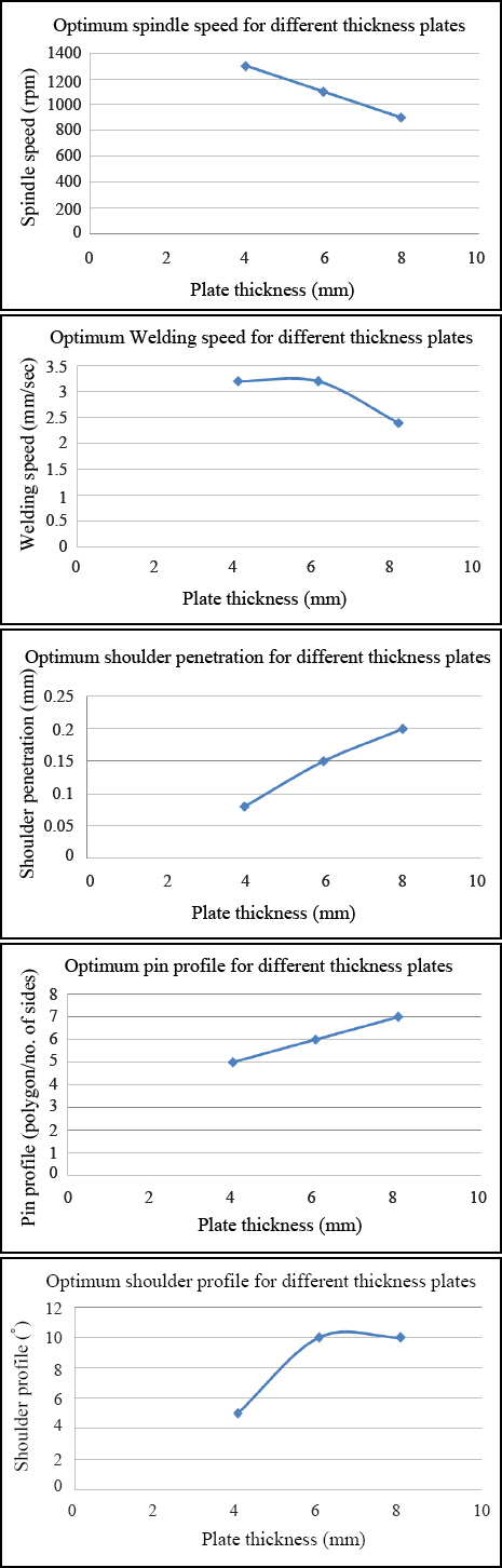
Optimum parameters’ plot (spindle speed, weld speed, shoulder penetration, pin profile & shoulder profile) for maximum tensile strength - different plate thicknesses

Optimum welding pulses in friction stir welding
Fig. 7 shows the friction stir welding pulses induced in various profiles of different tool pin sizes. The area of the inscribed circle and the envelope between the inscribed circle and circumscribed circle shown in Fig. 7 are respectively termed as a static area and dynamic area. The tool pin profile/polygon face edge increases, the static area increases and the dynamic area decreases while stirring. In the dynamic region, the actual material sweep was obtained30). Larger the dynamic area/material sweep leads to larger grain size. Smaller the dynamic area/material sweep leads to smaller grain size.
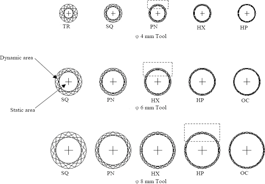
Pulses induced in various tool profiles of different tool sizes
The minimum number of tool pin striking edges/polygon edges produces a lower number of pulses. The dynamic area of the polygon with a lower number of face edges is high. Hence the larger volume of the material sweep was obtained, and this leads to larger grain size in the weld zone. However, the polygon with a lower number of face edges has a smaller static area. This smaller cross-section leads to tool breakage due to its lower shear strength and torque taking capacity. A larger number of polygon face edges in the tool pin profile produce a higher number of pulses. The dynamic area is comparatively lower, which leads to a decrease in grain size and an increase in the static area/shear strength/ tool life. The decreasing order of dynamic area approaches the smaller and refined grain sizes. After a certain point, no material sweep occurs for a large number of polygon face edges when it closely approaches the circular profile. Also, if the tool diameter increases the dynamic area and a material sweep or pulse volume are increased. The larger tool diameter requires more number of tool pin polygon edges to obtain the more refined grains because the same polygon profile gives the larger dynamic area, which leads to larger grain size. Fig. 7 shows that the optimum tool pin polygon face edge for the pin diameters of 4 mm, 6 mm and 8 mm was a pentagon, hexagon and heptagon to obtain good weld with refined grains.
4. Conclusions
The optimum friction stir welding parameters are found for fabricating butt joint configuration with 4mm, 6mm and 8mm thick AA 6068 - T6 plates. The weld pulses influence of various tool profiles on tensile strength and microstructure were studied and evaluated. The findings of this study are as follows:
1) The optimum process parameters for joining 4 mm thick plate which is found to achieve superior tensile strength are such as 1300 rpm spindle speed; 3.2 mm/sec weld speed; pentagonal pin profile; 0.08 mm shoulder penetration; and 5° convex shoulder taper.
2) Optimum process parameter levels for 6 mm thickness welded plate which is found to achieve greater tensile strength are such as 1100 rpm spindle speed; 3.2 mm/sec weld speed; hexagonal pin profile; 0.15 mm shoulder penetration; and 10° convex shoulder taper.
3) The optimum process parameter combinations for welding 8 mm thickness plate which is found to achieve better tensile strength are spindle speed of 900 rpm; weld speed of 2.4 mm/sec; heptagonal pin profile; shoulder penetration of 0.20 mm; and 10° convex shoulder taper.
4) The best pulses required to achieve a defect-free good weld range from 105 - 110 pulses/sec.
5) The microstructure evaluation shows that the high number of polygon pin faces helps to attain higher metal stirring in the weld zone and a fine grain structure was achieved, and the size achieved is between 3 μm to 6 μm. When the higher polygonal pin faces approach circular pin face, the metal distortion gets reduced due to the reduction of dynamic area and causes the formation of coarse grains, and that is more than 9 μm in size. This process leads to a reduction in weld strength.
Acknowledgement
The authors would like to acknowledge University Grants Commission (UGC) (Ref: No.: F/2016-17/NFO- 2015-17-KER-393), Government of India, Bahadur Shah Zafar Marg, New Delhi for proving fund for this experiment, and also like to acknowledge the faculty members of the Institute of Materials Joining, Shandong University, Jinan, China and Government College of Technology, Coimbatore, Tamilnadu, India.