Friction Stir Welding of EN 10130 Low Carbon Steel
Article information

Abstract
After evaluating the weldability of 1.5 mm thick EN 10130 steel sheets, the influence of friction stir welding parameters, i.e., rotation speed, tool advancing speed, pin diameter, and shoulder diameter on the properties of sound joints was examined. Using metallography, scanning electron microscope, tensile test, microhardness measurement, limiting dome height test, and forming limit diagrams, it was found that having a flawless joint requires the rotation and advancing speeds to be in the range of 500-1000 rpm and 30-160 mm.min-1, respectively. A design of experiment with 29 samples based on the Box-Behnken response surface methodology method with 5 center points was then utilized to maximize the tensile strength. Accordingly, the safe range and an optimized point for welding parameters were defined.
1. Introduction
Among novel welding processes, friction stir welding (FSW) has received widespread attention from many in various industries, including automobile industry for joining steel and aluminum alloys1). However, the major problem of sheets joined by FSW technique is the reduction in mechanical properties compared to base metal. This is usually due to the incorrect selection of welding parameters such as imprecise tool rotation speed, advancing speed, pin and shoulder diameters, tilt angle, preheat temperature, tool rotation direction (clockwise or counter clockwise), fixture and clamping system, tool geometry, etc.1-4). A flawless joint can only be obtained by selecting welding parameters in a limited range; otherwise, mechanical properties will suffer significantly5,6). However, selection of these parameters is highly dependent on sheet thickness and material type making each FSW process unique1,7). Jafarzadegan et al.8) investigated FSW of St37 steel and 304 stainless steel technique in constant advancing speed and 400 rpm and 800 rpm tool rotation speeds. They found that the sample welded with lower tool rotation speed had higher elongation and lower strength. Moreover, tungsten carbide (WC) particles were observed in the cross-section of the specimen welded by a higher rotation speed resulting in a lower joint ductility. Ghafarpour et al.2) joined 5083-H12 and 6061-T6 aluminum alloy sheets by FSW and optimized welding parameters including tool rotation speed, advancing speed, pin diameter, and shoulder diameter using design of experiment (DOE). They also determined a safe range for every parameter by performing limiting dome height (LDH) tests on the welded specimens and could maximize the formability of welded joints by optimizing the welding parameters. Yazdipour et al.9) joined 5083-H321 aluminum alloy and 316L steel sheets by FSW technique. They realized that by at higher advancing speeds, defects form in the cross-section of the steel sheet leading to a decrease in the joint strength. Ramesh et al.10) welded high strength low alloy (HSLA) steel sheets by FSW and studied the relationship between microstructure and tensile strength. They discovered that high advancing speeds decrease the join strength significantly. Cho et al.11) successfully welded type 409 ferritic steel by FSW. They found that stir zone microstructure is completely fine-grained and has very high strength which is due to recrystallization of shear deformation and evaluated temperature.
EN 10130 sheets are used widely in automobiles bodies12); thus it is required to have a great understanding of their weldability using conventional methods such as FSW. Following the evaluation of the weldability of EN 10130 joints using FSW in a previous work13), this paper investigates the effective parameters, i.e. tool rotation speed, advancing speed, pin diameter, and shoulder diameter and optimizes them using DOE. Then, the structure-property relationship is discussed in the EN 10130 sheets welded by optimum parameters.
In the present study, after evaluating the weldability of EN 10130 joints using FSW, the effective parameters, i.e. tool rotation speed, advancing speed, pin diameter, and shoulder diameter, were optimized using DOE. Then, microstructure, mechanical properties and joint ductility of EN 10130 sheets welded by optimum parameters were studied.
2. Experimental procedure
In order to prepare specimens, FSW process with different parameters was performed on EN 10130 rolled steel sheets (168 MPa yield strength and 315 MPa tensile strength) with 1.5 mm thickness and the chemical composition given in Table 1. Tungsten carbide tool with conical pin (Fig. 1) was used for welding. After FSW process, samples were ground and etched in 2% nital solution for 20 s for metallography examination. Microstructural evaluations were carried out by optical microscope and VEGA/TESCAN-XMU scanning electron microscope (SEM) at 20.00 kV high voltage. Tensile test samples were prepared based on ASTM E8 standard. Measurement of Vickers microhardness was performed under 100 g load for 15 s.

Chemical composition of EN 10130 steel
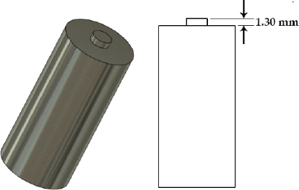
The geometry of the WC tool
In this investigation, LDH test was employed to examine the formability of the welded sheets. A mandrel descending at 2 mm.min-1 was used for this test2). When the sheet was torn, it resulted in drop of the force index indicator of the device. At this stage, the applied force onto the mandrel was removed. In this situation, the moving distance of the mandrel is equal to the maximum formability limit of the sheet.
Forming limit diagrams (FLDs) were employed to investigate the formability of joints based on ASTM E 2218 standard14). For this test, sheets welded by optimized parameters were used. These 0.1 mm thick sheets with the diameters of 0.1 and 5 mm and center-to-center distance of 5 mm were manually extracted from the 1.5 mm thick welded sheets by a circular pattern. In this research, the major and minor engineering strains were calculated using12,14):
where Lo is the initial length, Lf is the final length, Wo is the initial width, and Wf is the final width.
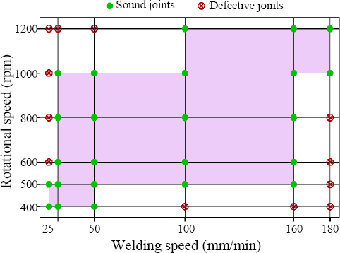
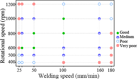
In response surface methodology (RSM), the response resulted from changing effective parameters while keeping control parameters constant is monitored. In this study, tensile strength was considered as the response while rotation speed, advancing/traverse speed, pin diameter, and shoulder diameter were the effective parameters. After evaluating 36 welded samples with the parameters shown in Fig. 2, it was found that sound welds can only be attained when the tool rotation speeds is 500-1000 rpm and advancing speeds is 31.5- 160 mm.min-1. Based on these tests and data gathered from previous studies1,8,12,15,16), the upper, intermediate, and lower levels were selected (Table 2). DOE was done by Design-Expert software via Box–Behnken design with 5 center points. Table 3 displays 29 runs along with their obtained ultimate tensile strength (UTS) as the response.

Upper, intermediate, and lower levels of examined factors

Designed experiments by Box-Behnken method and ultimate tensile strength results in tensile test
3. Results and discussion
The effects of rotation and advancing speeds on joint strength are evident in Fig. 3a. As reported by other researchers16,17), rotation speed has a higher influence on joint strength as compared with the advancing speed. According to this figure, the highest strength can be gained with a rotation speeds of 700 to 875 rpm and advancing speeds of 60 to 90 mm.min-1. According to Fig. 3a-f, in terms of their effect on the response, parameters can be sorted as tool rotation speed, advancing speed, pin diameter, and shoulder diameter. The sufficiency of the DOE model is investigated and the result is presented in Table 4.
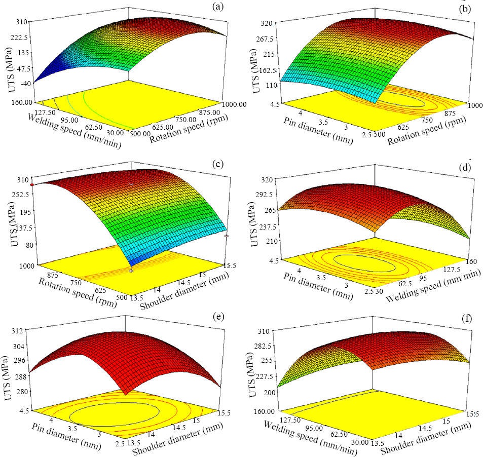
Effect of different welding parameters on the tensile strength of welded sheets: (a) tool rotation speed and linear advancing speed, (b) tool rotation speed and pin diameter, (c) rotation speed and shoulder diameter, (d) tool linear advancing speed and pin diameter, (e) shoulder diameter and pin diameter, and (f) shoulder diameter and tool linear speed. (a) and (b) are reprinted from13) with permission from Journal of Solid Mechanics in Engineering

Predicted response by RSM and obtained experimental result
3.1 Metallography and microstructural examinations
Fig. 4 a shows the microstructure of EN 10130 steel base metal. This microstructure contains about 2% pearlite and 98% ferrite. When welded sheets under optimized conditions (Table 4) were studied, it was observed that different zones with various characteristics were formed due to generated heat and plastic deformation. As demonstrated in Fig. 4b as a result of welding 3 new zones are formed: (1) stir zone (SZ), thermo-mechanically affected zone (TMAZ), and heat affected zone (HAZ).

Microstructure of (a) EN 10130 low-carbon steel base metal and (b) the joint welded by optimized parameters
In SZ, grains which are 10-20 times finer and more homogenized than those of the base metal are formed. This is due to the recrystallization which occurs due to severe plastic deformation. According to literature18,19), the temperature in SZ can reach 900 to 1100°C. This, in conjunction with high severe plastic deformation, led to formation of fine and homogenized grains as a result of recrystallization. The plastic deformation increases the density of crystalline defects, especially dislocation density. In the presence of high temperatures resulted from the friction between the tool and workpiece dynamic recrystallization becomes inevitable and new fine grains form resulting in increased hardness and strength20).
SEM was used for better evaluation of the microstructure and the results are presented in Fig. 5. Due to the heating cycles, grains size in the HAZ is larger than that of the base metal. However, as a result of the thermomechanical cycles, the grain size in TMAZ is about two times smaller than the base metal. In comparison, SZ has very fine grains due to the dynamic recrystallization.
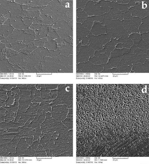
SEM of different zones of welded joint: (a) base metal, (b) HAZ, (c) TMAZ, (d) SZ
3.2 Tensile properties
The stress vs. strain curves for the base metal and the joint welded by optimized parameters are shown in Fig. 6. The welded specimen fractured in base metal in the advancing side. However, the specimens welded by parameters out of the safe range were mostly fractured from the weld zone at much lower stresses and elongations.

Stress-strain diagrams of base metal and welded specimen with optimized parameters
3.3 Microhardness measurement
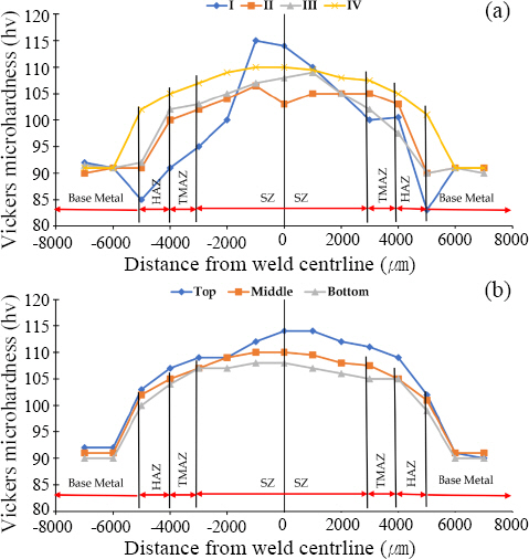
Fig. 7a shows the hardness profile of samples labeled as I, II, II, IV welded by parameters shown in Table 5. All samples show a similar trend which is the increase of hardness from base metal to SZ flowing the microstructure of the regions discussed previously. The only exception is Sample I. This sample has the highest value of hardness in SZ. Previous studies1,8,21) suggest sometimes enhanced local hardness in SZ can be due to extremely high heat input followed by the detachment of tungsten carbide pieces and formation of iron/tungsten composites. Also, this sample has hardness values less than the base metal in the HAZ which is due to excessive heat input and grain coarsening.

Welding parameters for microhardness samples
Fig. 7b shows the hardness profiles at the bottom, center, and upper part of the same sample (sample IV). It is discussed in the literature15) that hardness in the bottom of the sample is lower than center and upper parts because of different cooling rates; the top parts undergoes the fastest cooling and thus, has the highest hardness due to the finer grains.
3.4 LDH test
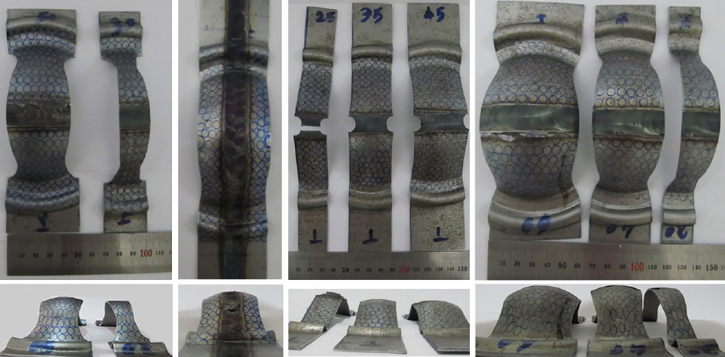
For this test, initially EN 10130 base metal sheet was tested. For this sample, the gage showed 45 mm upon tearing (Fig. 8a). Then, two sample welded using optimized parameters were tested in both face and bead sections (Fig. 8b and Fig. 8c). For these samples, the gage was 40 mm. This amount of deformation compared to base metal confirms the efficiency of the welding process. As expected, tearing of the joined sheets welded with non-optimized parameters occurred in the nugget, as shown in Fig. 8d.

Samples for LDH test: (a) raw EN 10130 sheet; (b) face of welded sample under optimized parameters; (c) bead of sample welded under optimized parameters, and (d) welded sample under non-optimized parameters
As confirmed by a recent study12), Fig. 8 confirms that welding reduces ductility. This observation also endorses the stress-strain diagram in Fig. 6 where welded sample showed a lower ductility than the base metal.
3.5 Forming limit diagrams
To draw FLDs, circular signs which were completely or partially placed on the necked area were considered unacceptable and circles distanced equal or more than one diameter from necked area with no necking effect were considered as correct values, i.e. safe points. FLDs were drawn by interpolation of the safe points14). Circles placed in the necking area or in the adjacent torn area are displayed as unsafe points in these diagrams.
Considering the fact that increasing thickness increases ductility and welding decreases it12,22), it can be concluded that the value of FLD0 for EN 10130 base metal sheet with the thickness of 1.5 mm is higher than 0.48 of that of the welded sheet. Fig. 9 shows the FLD of EN 10130 sheets with 1.5 mm thickness used in this study. If the strain induced by FSW is above the forming limit curve in Fig. 10, the sheet will tear resulting in a defective weld.
FLD samples used for determining the minor and major principal strains
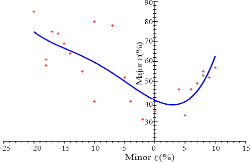
FLD of EN 10130 steel sheets with thickness of 1.5 mm welded by FSW
3.6 Effect of tool rotation and linear advancing speeds
According to Terry’s reports23), advancing speed should be changed together with rotation speed, otherwise defects, such as cavity and porosity, are created in the weld nugget.
According to Table 6, 20 experimental tests in the present study were carried out to evaluate the effect of simultaneous change of these two parameters. In these tests, the shoulder and pin diameter were constant at 14.2 and 3.9 mm, respectively.

Experimental tests designed to determine the relationship between rotation and advancing speeds
The results are presented in Fig. 11. As can be seen in Fig. 11a, the highest strength was reached within the range of 600-1000 rpm in any linear advancing speed except for 31.5 mm/min. Also, according to the Fig. 11b, at constant rotation speeds, the highest and lowest strengths were obtained at the rotation speed of 50 and 160 mm.min-1, respectively. The reason is attributed to different generated heat rates and amounts of mechanical work in the joint2).

UTS versus (a) various advancing speeds at constant rotation speed and (b) rotation speeds at constant advancing speed
As shown in Fig. 11b, in the range 50-100 mm.min-1, advancing speed provides a suitable friction in the weld region. Too much friction and, consequently, too high heat inputs can cause grain coarsening and formation of porosities due to high plastic flow24). Thus, the cause of low strength in advancing speeds lower than 50 mm.min-1 can be attributed to the high heat input and formation of the mentioned defects.
According to Fig. 11a, at a constant rotation speed (except for 500 rpm), the highest strength was obtained at a linear advancing speed within 50-100 mm.min-1 range. Thus, it can be concluded that the samples welded with tool rotation speed of 600-1000 rpm and advancing speed of 50-100 mm/min have the maximum tensile strength. Optimized parameters by DOE experimental design were in this range, as shown in spot A of Fig. 12. These results approve the validation of selected factors, experimental design, obtained mathematical function, and more importantly, the optimization process.
”Safe” ranges for rotation and advancing speeds
4. Conclusions
Welding parameters for joining EN 10130 low-carbon steel by FSW were optimized, and the following results were obtained:
- The coarse-grain microstructure of the base metal was turned into a fine microstructure with coaxial grains as a result of FSW.
- As a result of recrystallization, the stir zone showed higher tensile strength and hardness compared with the base metal.
- The optimized FSW parameters for welding 1.5 mm thick EN10130 sheets using a pin with 1.3 mm pin height were 14.2 mm shoulder diameter, 3.9 mm pin diameter, 800 rpm rotation speed, and 80 mm/min advancing speed.
- Using limiting dome height, forming limit diagram and accordingly the maximum allowable FSW-induced strain showing the safe ranges for the two most important parameters, i.e. rotation and advancing speeds, were determined. Welding within this safe parameter space will not result in any defective joint.
ORCID
ORCID: Akbar Alimohamady: http://orcid.org/0000-0003-1827-2517
ORCID: Abbas Eghlimi: http://orcid.org/0000-0003-3178-8147
ORCID: Mohammad Alipour Behzadi: http://orcid.org/0000-0003-1798-8986
ORCID: Javad Mohammadi: https://orcid.org/0000-0003-0333-9889