A Review on Twin Tungsten Inert Gas Welding Process Accompanied by Hot Wire Pulsed Power Source
Article information

Abstract
Tungsten Inert Gas (TIG) welding process is used in the industry due to its positional suitability, good control over metallurgical and mechanical properties and weld integrity. It makes this process more suitable to weld the root pass in the piping industries. However, there is a remarkable limitation to increase the welding current beyond a certain limit in the conventional TIG welding process due to limited current carrying capacity of a single electrode and higher arc pressure. This limits its productivity. To combat it, Twin TIG (T-TIG) welding process is introduced where the two tungsten electrodes are present in one torch. The two separate and synchronized power sources are connected to the two electrodes. To increase the metal deposition rate, the hot filler wire is used because it reduces the requirement of heat from arc plasma. There is another advancement in the TIG welding process which incorporates pulsed power source assisted welding process to control weld bead geometry, microstructure and to weld dissimilar material. This paper presents the effect of parameters of T-TIG, hot wire, and pulsed current welding processes when performed separately. A novel welding set up is proposed to weld dissimilar material with weld integrity. This paper suggests that when these three techniques are used simultaneously by meticulous studies of their process parameters with automation, an outperformed technique can be evolved which multiples the individual advantages of the three processes.
1. Introduction
In this competitive scenario, industries are forced to adopt the techniques that provide higher productivity without losing quality. Conventional TIG welding process produces sound weld with high integrity with base metal. But due to the lack of productivity its usage is mainly limited to weld root pass, where back side chipping is not possible like in piping industry. To increase the performance of TIG welding process, developments like A-TIG (Activated TIG), T-TIG (Twin TIG), S-TIG (Super TIG), hot filler wire, usage of pulsed heat input, hollow electrode and many others are being carried out1). This paper aims to present T-TIG welding process when it is connected with pulsed power source and employed with application of hot filler wire. It will be very interesting to investigate the combined effect of these three techniques to multiply the advantages of individual technique. The literature survey is carried out in tabular form to extract and compare the conclusions.
2. Basic features of T-TIG, Hot wire and Pulsed power source
2.1 T-TIG welding process
In the TIG welding process if current is increased then arc pressure increases which results erratic and unstable arc. It forms undercut and bead humping thus weld bead quality decreases2,3). So, there is a limit beyond which current cannot be increased in TIG welding process. Recently to overcome this limit Japanese researchers developed a method namely T-TIG welding process. In it, there are two electrodes connected with the two independent power sources in single torch. This not only increases current carrying capacity of T-TIG welding torch but also decreases the arc pressure4,5).
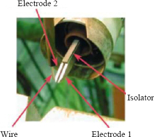
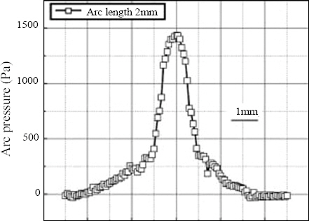
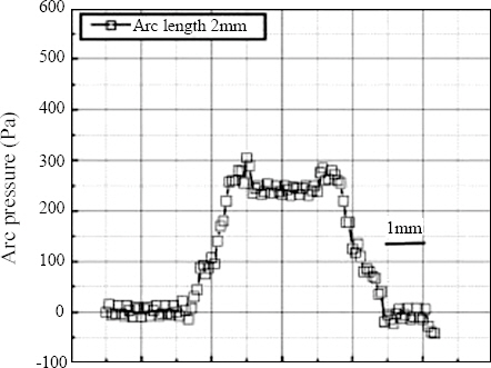
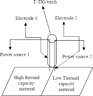
Fig. 1 represents the schematic diagram of T-TIG welding torch. Here two electrodes are insulated electrically by means of a ceramic insulator so that the arc can exist without fluctuation and interruption. Due to Lorentz force, arcs will be attracted to each other. Fig. 2 and 3 presents the comparison of the arc pressure when TIG and T-TIG torch is used respectively. From these figures it can be observed that the arc pressure and pressure gradient is very low as compared to single electrode for the same current. It can be observed that for the same current T-TIG occupies larger area of anode as compared to TIG welding process3).
2.2 Hot filler wire
In hot filler wire welding, filler wire is heated electrically by resistance heating with separate power source in case of the TIG welding process. By preheating the filler wire, required heat input from the arc reduces to a great extent and higher deposition rate can be achieved even at lower arc current6). Fig. 4 represents the principle of hot wire welding process. As per this figure the important components of hot wire process are:
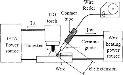
1) Wire feeder.
2) Torch which supplies current to wire.
3) Power source to heat the wire.
4) Power source for generating arc.
There has to be a balance between all these component’s parameters to establish stable arc. The polarity of hot wire power source plays a major role with location of hot wire whether front or back to the arc7).
2.3 Pulsed Heat Input
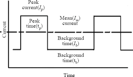
After 1960 it has been observed that the conventional arc welding processes fail due to evolvement of advance material and complex weld edge preparation. When the thermal capacity of material to be welded is different due to either dissimilar thickness or thermal conductivity, constant heat input raises welding defects like burn through or lack of fusion. To avoid the same, heat is provided at discrete level; low level or background current and high level or peak current. Fig. 5 describes the nomenclature of waveform in which peak current is provided for predefined time and responsible for melting of material. After pulse on duration, current is reduced drastically at base level. During base level, ideally no melting is occurred and only solidification is done. When pulsed power source is controlled in a synergic manner it can change the pulse frequency, pulse on time, peak current and background current independently. There are mainly two types of pulsing viz. thermal and droplet pulsing. Former is used in the TIG welding process to weld dissimilar materials and latter is used in the MIG (Metal Inert Gas) welding process to attain the spray mode of metal transfer at lower mean current than in constant current MIG welding process8).
3. Literature Survey
To identify the research gap, derive qualitative conclusion and identify the best combination of these three techniques, the literature survey is done separately in Table 1, 2 and 3 respectively.
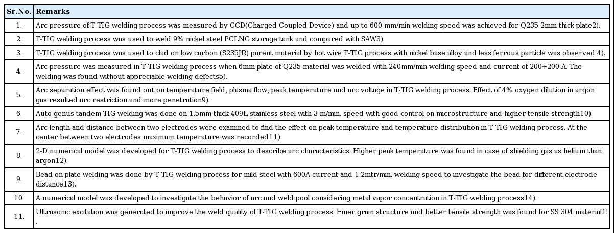
Major literature survey of dual/twin/tandem electrodes
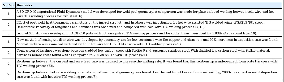
Major literature survey of hot filler wire welding techniques
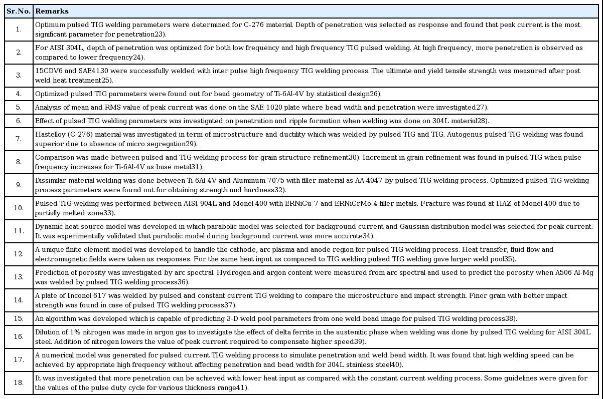
Major literature survey of pulsed heat input with TIG welding process
4. Effect of individual process parameters on welding
4.1 Pulsed power source parameters influencing weld bead properties.
Pulsed power source differs due to its discrete nature to supply current or merely voltage. Albeit other conventional welding parameters are important in pulsed power source welding like travelling speed, electrode diameter, etc. following additional pulsed power source parameters influences more in welding qualities.
a) Peak Current
b) Background Current
c) Frequency
d) Duty cycle (% of time for peak current)
4.1.1 Effect of pulsed welding process parameters on mechanical properties
For magnesium AZ31B and AZ61A alloy, it was found that peak current is most influencing parameter that affect the tensile strength48,49). One contradictory result was found which indicated that when peak current increases the tensile strength reduces for strain hardened Al-6.7Mg alloy. The reason behind it was the generation of high heat input that formed the coarser grain and reduced the strength50). For AA6061, it was investigated that peak current is more sensitive at optimum value of tensile strength i.e. if the value of peak current is varied marginally near the optimum value, the change in tensile strength is more51).
Up to certain level if peak current along with pulse frequency (up to 6Hz) is increased, impact strength of weldment is increased for titanium alloy52,48).
There should be an optimum value of pulse frequency at which the tensile strength is higher. Due to high frequency, large number of peak current components is involved per unit time which confirms adequate heat input. But for very large frequency the welded material will not exist in thermal equilibrium and agitate the prior semi solidified material which results adverse effect on strength50).
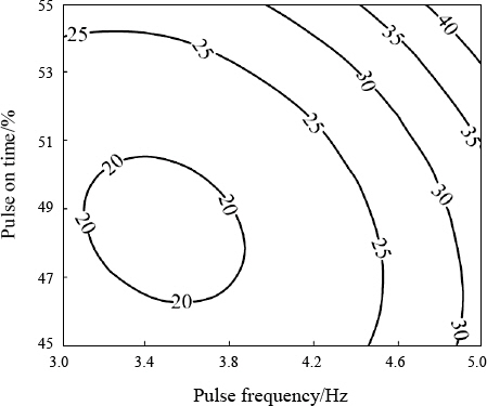
It has been investigated that there is strong interaction between pulse on time and pulse frequency on tensile strength of AA6061 as shown in Fig. 6.
4.1.2 Effect of pulsed parameters on metallurgical properties
As per equation (1) mean current which is used to find heat input is calculated by peak current so it also governs the size of grain and other metallurgical properties.
As in case of pulsed current welding, the peak current along with background current, frequency and duty cycle influences the heat input and hence microstructure. In double pulsed welding it is found that the value of peak current should be optimum to achieve finer grain for T-joint welding53).
Lower duty cycle results in finer microstructure due to large time available for cooling50). The optimum value of duty cycle was resulted 50% improvement in grain refinement for AZ31B magnesium alloy49).
It is also observed the interaction effect of background current and peak current for grain size at fusion zone of AA606152). There was no appreciable change in macrostructure of weld joint found due to variation of background current for AZ61A magnesium alloy50).
4.1.3 Effect of pulsed parameters on weld bead geometry
It was observed while welding of SAE-1020 material that when peak current was increased by keeping the same mean current, the width of the weld bead will increase and no effect on weld penetration. But when peak current was increased by decreasing the mean current it reduced the weld bead penetration but no change in weld bead width42). It is also found that when peak current is used at higher side it increases both weld bead ripple formation and penetration42-44). It is also observed that at extreme low and high frequency, peak current has less significance on aspect ratio (weld bead width to penetration ratio)45). For Ti-6Al-4V, it is found that for achieving optimum results of weld bead and height, the peak current should not be operated at extreme high and low value46). Fig. 7. explains the all aspect of weld bead geometry affected by peak current while other welding parameters are constant47).
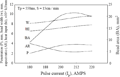
Fig. 8 represents the ripple height and pitch value of weld bead for different values of pulse frequency. It can be inferred that for higher value of pulse frequency the lower pitch length and height is obtained54). For low frequency (6-10Hz) the depth of penetration is lower as compared to high frequency (150-250Hz) for AISI304L45). For higher frequency, large weld region was found as compared to low frequency50).
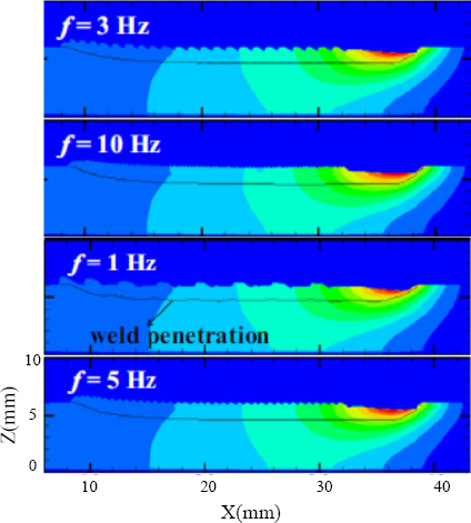
For Ti-6Al-4V material it has been observed that if the frequency is increased from 1 to 5 Hz grain refinement occurs speedily from prior beta phase and for the same material it also influences impact strength greatly55,47). It was investigated that there should be an optimum level for which the grain size is fine. At very small frequency, the mechanical and thermal disturbance is very small and it will not break the grain boundary50).
Duty cycle is defined as the ratio of time duration for peak current and background current. It is also represented by pulse on time i.e. the duration of time for which peak current is supplied. For large duty cycle it is observed weld bead with large ripple width and depth4).
The value of background current should be chosen appropriately so that the arc does not extinct when the pulse off time is active. A little research has been found which focuses only background current as prime study. Certainly, the ratio of Ip/Ib is essential for predicting weld bead geometry54).
So, from above studies it can be concluded that peak current is a prime factor contributing heat input. The role of background current is to prevent the extinction of arc. Other important interactive effect of peak and background current are the ratio of it which decides the amount of thermal fluctuation. Pulse frequency decides the microstructure and consequently mechanical properties such as impact strength, tensile strength. Duty cycle also has interactive effect with pulse frequency to control the grain size by varying the cooling time.
4.2 Hot wire welding parameters influencing weld bead properties
The filler material is heated outside the weld pool before it comes into contact with arc plasma. This reduces the amount of heat required to melt the material from arc plasma. Little research was found to analyze the effect of hot wire welding parameters on responses. However, Table 6 represents the effect of influencing parameters of hot wire (HW) welding by extractive and intensive literature survey. In hot wire welding the additional heat is provided by resistance heating. As per equation (2) the value of resistance heating can be calculated.
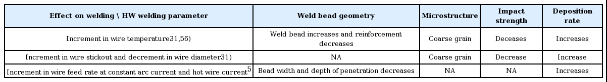
Hot wire process parameter effects on welding
Here I is the wire current, R is the resistance of wire and t is the time for which current is passed.
Here ρ is the specific resistance or resistivity of wire, L is the stick-out-length and A is cross sectional area of filler wire. So, to increase the resistance heat the value of L and d (diameter of filler wire) should be chosen accordingly. Longer stick-out-length increases the heat input but simultaneously creates more corrosion tendency due to increased temperature. Again, the lower diameter wire reduces the deposition rate. So, the value of stickout-length and wire diameter should be optimum.
Hot wire current, arc current and wire feed rate are strongly interactive. Fig. 9. shows that increment in wire feed rate has to be compensated by increasing arc and hot wire current. It is also investigated that when the hot wire applied at rear of arc it decreases embrittlement of weldment due to low cooling rate and reheating reduces temperature gradient57,58).
Effect of deposition rate due to variation in arc current, hot wire current and wire feed rate58)
4.3 T-TIG welding parameters and its effects on welding
As discussed, a little research has been done experimentally for T-TIG welding. However, some numerical and analytical models have been developed to understand the effects of T-TIG welding process parameters on welding qualities. To investigate the effect of process parameters on welding, the literature survey has been done as per table 1. On the basis of it following are the important process parameters for T-TIG welding process.
(a) Leading and trailing arc current
(b) Distance between two arcs
(c) Polarity of two arcs.
4.3.1 Effect of leading and trailing arc current
The leading arc current is more sensitive to penetration than trailing arc current. The ripple formation and surface appearance of weld bead is controlled by trailing current.
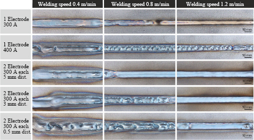
4.3.2 Effect of distance between two arcs
The separation between two electrodes has a significant effect on temperature and arc plasma flow field but a non-significant effect on peak temperature. As shown in Fig. 10. if the distance between two electrodes increases, the humping of weld bead and molten metal decreases for slower speed. But when simultaneously the speed is increased, the amount of molten metal increases. The effect of metal vapor due to electrode separation is analyzed and it is found that having 9 mm separation between electrodes creates intensive constriction of arc and temperature profile9).
4.3.3 Effect of polarity of two electrodes
If the two electrodes are having opposite polarity then it is observed that the arc is constricted and controlled as per Lorentz effect. The arc force is also higher as compared to similar polarity2).
It has been also observed that increasing in wire extension value leads to increase in melting rate13).
Conclusions
From the literature survey, it can be concluded that little research is available that combines the three unique characteristics namely twin electrode, usage of hot filler wire and pulsed power source of TIG welding process. Hence following conclusive remarks can be made which identifies the special features of individual and then in combined form.
T-TIG welding is developed to increase the current capacity of electrode and thus to increase the metal deposition rate. In single electrode TIG welding process as current increases, arc pressure increases. This unstable arc causes welding defects like undercut and burn through. But T-TIG welding process reduces arc pressure drastically when appropriate distance is kept between two electrodes. As this process is used at high speed, maximum advantage can be achieved in automated welding.
It is observed that most of the heat from TIG arc plasma is utilized to heat the filler metal as well as base material from room temperature to melting point temperature. By using hot filler wire, requirement of heat from plasma can be reduced and deposition rate can be increased.
In pulsed welding the net heat input is lesser than constant current welding process. This reduces the grain size and increases impact strength. From literature review it is observed that it also increases the depth of penetration, provides good strength for dissimilar material by thermal pulsing at high frequency.
So, there is a high potential that deposition rate can be increased drastically by combining hot wire with T- TIG welding process. And if pulsed power source adds into it then there is a good potential to weld dissimilar materials, to obtain control on grain size and weld bead productively. Automated T-TIG can be an attractive option to replace SAW welding process for cladding due to lower dilution, optimized bead height and highly control on parameter resulting an exceptional weld quality
However, the limitation of integration of above three processes is high capital cost and large number of influencing process parameters involved. So, large numbers of experiments are required to identify the relationship between process parameters and on output response like mechanical properties, weld bead geometry, etc.
Proposed T-TIG Process for dissimilar thermal capacity material either due to dissimilar thickness or thermal conductivity
As in T-TIG welding process, two independent power sources are there and that can operate at different current. So, with this unique characteristic, it is possible to supply lower current to high thermal capacity and higher current to low thermal capacity as shown in Fig. 11. This combination can meet the stringent requirement of dissimilar welding.
Block diagram for proposal of dissimilar material