Warning: fopen(/home/virtual/kwjs/journal/upload/ip_log/ip_log_2024-03.txt): failed to open stream: Permission denied in /home/virtual/lib/view_data.php on line 88 Warning: fwrite() expects parameter 1 to be resource, boolean given in /home/virtual/lib/view_data.php on line 89 A Review of Joining Processes for High Strength 7xxx Series Aluminum Alloys

A Review of Joining Processes for High Strength 7xxx Series Aluminum Alloys

Article information

J Weld Join. 2017;35(6):79-88
Publication date (electronic) : 2017 November 20
doi : https://doi.org/10.5781/JWJ.2017.35.6.12
* Joining R&D group, Korea Institute of Industrial Technology, Incheon, 21999, Korea
** Dept. of Materials Science and Engineering, Seoul National University, Seoul, 08826, Korea
Corresponding author : chkim@kitech.re.kr
Received 2017 September 19; Revised 2017 October 16; Accepted 2017 October 17.

Abstract

The applications of high strength aluminum alloys in automobile manufacturing has been growing with increasing demands for fuel efficiency and reduction of CO2 emissions. Aluminum alloys pair a high specific strength with relatively low cost compared to similar lightweight metals. The 7XXX series aluminum alloys in particular exhibit a high strength in excess of 500 MPa after heat treatment. However, these alloys exhibit poor weldability because of their high crack susceptibility, high thermal expansion coefficient, and low vaporization-temperature of alloying elements such as Zn and Mg, which readily contributes to weld defects such as cracks and porosity. In this paper, the mechanical properties and microstructural characteristics of 7XXX aluminum alloys are related to welding processes and reviewed for better understanding of the welding characteristics of this high strength alloy.

1. Introduction

In order to accommodate stricter environmental regulations, technological advances in high fuel efficiency vehicles have been constantly demanded of the automobile industry. Automotive bodies consist of a body in white (BIW), which is the structure of the vehicle, and hands-on parts such as the doors, hood, and trunk cover. These parts typically constitute about 30 % of the overall weight of a vehicle. Therefore, the reduction in the weight of automotive bodies is critical for the improvement of fuel efficiency1). At the same time, the weight of additional components required for safety, convenience, and emotional response is continuously increasing. These applications can raise the total weight of a vehicle, especially in high-end vehicles. For this reason, many carmakers are using more nonferrous lightweight materials such as aluminum, magnesium, and plastic in automobile bodies.

Aluminum alloys constitute a fairly a representative class of lightweight material, and their applications in automotive car bodies are expanding. For car bodies, Al-Mg alloys (5XXX series) and Al-Mg-Si alloys (6XXX series) are typically used due to their high strength and formability2,3). Al-Zn alloys (7XXX series), which are typically used in aircraft parts, possess a strength over 500 MPa through the formation of strengthening precipitates4). Recently, research into the application of 7XXX alloys to automobile parts has been pursued5-7).

The 7XXX series aluminum alloys are known to be difficult to conventionally weld using fusion processes like arc, resistance spot, and laser welding8,9). The weldability of various aluminum alloys is summarized in Table 110). The weldability of 2XXX and 7XXX aluminum alloys is poor when fusion welding because of the likelihood of hot cracking due to large mush zone created during the welding process.

Weldability of various aluminum alloys10)

The 7XXX series aluminum alloys are usually heat- treated by an artificial aging process, which ensures a high strength. When welding, the physical properties of the aluminum welds are compromised due to the annealing and tempering of the heat affected zone. Additionally, the heat affected zone of an aluminum alloy is wider than that of a carbon steel owing to aluminum’s higher thermal conductivity. When welds possess the metallurgical discontinuities caused by these factors, the strength of the connected part is degraded, and corrosion resistance may be compromised in some cases11).

Mechanical fastening could be used to join the components of a vehicle body as an alternative to welding. However, in spite of its intuitive and simple nature, mechanical fastening possesses many disadvantages, such as indentations or protrusions in the connection appearance, low fatigue cracking resistance due to stress concentrations, easy opportunities for crevice corrosion, and increase in weight by necessitating wider flanges at connections.

Therefore, the selection of a proper welding process is a matter of great importance in the assembly of a car body. As shown in Table 2, the evaluation of material weldability using various welding processes has been reported to this end11-39).

Research into the welding and joining of 7XXX series aluminum alloys over the last ten years

In this paper, we review and summarize the current state of welding research conducted on 7XXX series aluminum alloys using various welding processes. The arc welding and laser welding methods are selected as the considered fusion welding processes, and friction stir welding is chosen as the considered method of solid-state welding. The characteristics of each process are analyzed, and the resulting mechanical and morphological variations are then compared.

2. Arc welding characteristics of 7XXX series aluminum alloys

In the last decade, only a few studies have been published on the arc welding of 7XXX series aluminum alloys. In this section, the weldability of these alloys using gas tungsten arc welding (GTAW) and gas metal arc welding (GMAW) fusion welding processes are discussed.

When arc welding, proper selection of filler material is critical as it affects the metallurgical and mechanical properties of the ensuing welds. General guidance on filler metal selection for the GMAW process is provided in Table 340). Typically, a 4XXX filler wire containing Si is used in order to suppress hot crack propagation. In other cases, 5XXX filler wire is used to obtain joint strength31). In some of the research reviewed, the use of 2XXX filler wire has also been reported20).

General guidance on filler metal selection modified from reference40)

A typical fusion weld can be divided into a fusion zone (FZ), a partially melted zone (PMZ), a heat affected zone (HAZ), and the base metal (BM). Because the arc welding process applies a relatively high heat input, morphological changes around the welds can be easily identified. Fig. 1 shows the typical structure of a GTAW weld.

Fig. 1

Optical micrographs of as-welded joints: (a) base metal, (b) fusion zone, (c) heat affected zone, (d) columnar grain at the partially melted zone, and (e) incipient melting at the partially melted zone33,35)

The BM is a metal sheet formed by the rolling process. The grains of the BM are accordingly elongated with fine particles such as MgZn and Mg32(Al,Zn)49 precipitated and dispersed throughout14,33). After welding, this as-rolled structure disappears because the high temperature approaches the melting temperature. In its place, an equiaxed dendritic structure is formed at the core of the FZ due to the rapid cooling rate (Fig. 1(b)). The precipitation dissolution and texture coarsening within the grain boundary has been confirmed as shown in Fig. 1(c). In the PMZ, a columnar structure is developed near the FZ as shown in Fig. 1(d). Balasubramanian et al. observed that this precipitation was partially dissolved, and that the meta-stable phase was transformed to the stable state. The large temperature difference between the solidus and liquidus formed grain boundary melting, as shown in Fig. 1(c). They also mentioned that hot cracking could potentially be generated in the PMZ12,21).

Table 4 gives the hardness profile along the fusion weld in a 7XXX aluminum alloy. The hardness value of the weld is clearly lower than that of the base metal. The difference in the hardness of the FZ in welds produced by GMAW and GTAW processes was not significant despite the different levels of heat input. The average hardness of the FZ was 84 Hv, which corresponds to about 60 % of that of the base material, which was 138.8 Hv.

Vickers hardness and tensile strength of arc welded specimens without post aging12,35,39)

The observed failure strength of the weld was about 290 MPa with a joint efficiency of 58 % of that of the base material. The joint efficiency of GTAW process was observed to be about 10 % higher than that of GMAW process because the heat input of GTAW is relatively small. As shown in Table 5, both the hardness and strength increased after artificial aging due to the nature of the aluminum alloy. Still, the lowest hardness was measured at the FZ, even after aging heat-treatment.

Vickers hardness and tensile strength of arc welded specimens with artificial aging12,35,39)

3. Laser welding characteristics of 7XXX series aluminum alloys

The welding defects reported when laser welding 7XXX series aluminum alloys were underfill, pore, and cracking, as shown in Figs. 2 and 3. The laser welding process requires a small heat input than arc welding process by applying an integrated high-density energy beam. However, this high-density beam increases the possibility for the material vaporization during the welding process. As a result, compared to the arc welding process, the laser welding process is more likely to generate underfill20,36) and porosity26,27).

Fig. 2

Macro-section images of the transverse weld produced by (a) autogenous laser welding and (b) laser/GMAW hybrid welding20)

Fig. 3

Weld defects (a) transverse cracking on the top bead of an Al7075 laser-arc hybrid welded sample, (b) a typical HAZ crack in laser welded Al7075 (c) X-ray radiography showing the extent of porosity in laser-arc hybrid welded Al7075-T651, and (d) X-ray radiography of laser welds supplied with 4043 cold wire18,19,25)

It is difficult to control these defects using the autogenous laser process. As a result, the laser-arc hybrid welding process was introduced to reduce these defects by adding a filler wire. The supply of filler wire was not only found to improve the bead shape and quality, but also suppressed the formation of hot cracking when an adequate filler metal was selected.

The regions of laser welds can also be divided into an FZ, PMZ, HAZ, and BM. An equiaxed structure is formed in the center of the FZ as shown in Fig. 7, and an elongated columnar structure is generated at the PMZ which is narrower than that of the PMZ resulting from arc welds. In the HAZ located behind the PMZ, coarsened grain was observed to form due to thermal conduction.

Fig. 7

Image showing the microstructure of a laser- GMAW hybrid weld on an Al7075 alloy. The weld was made with an Al5754 filler wire at a welding speed of 80 mm/s20)

Hu et al. reported that cracks could develop on the bead surface when the arc current increased in the laser-arc hybrid welding process18-20). Ola et al. further explained the causes of many internal defects25). The formation of pores within the welds was found to be affected by the presence of shielding gas, and it was confirmed that Ar gas is more effective than He gas for the reduction of porosity. Additionally, the generation of internal pores was found to increase in hot wire feeding applications; when cold wire was supplied, internal pores were observed to decrease significantly25).

Compared to the autogenous laser process, crack formation in the HAZ was reduced when the laser-arc hybrid process was applied, as shown in Fig. 4. However, cracks were observed to increase when cold wire was fed into the weld pool. Ola et al. proposed a compromise scheme by adding cold wire to a preheated weld joint25), demonstrating that in the case of the laser-arc hybrid process, sound welds could be achieved by selecting the proper working conditions18-20).

Fig. 4

The length of intergranular cracking in the HAZ under various welding process (modified from reference)25) (Note: “LBW” indicates “laser beam welding”; “CW” indicates “cold wire”; “L-A” indicates “laser-arc”; “BH” indicates “base metal preheating by laser”)

Most tensile tests of laser-welded 7XXX specimens resulted in fracturing at the FZ, however, the overall strength of the specimens was typically higher than that of the arc welded specimens. The average tensile strength of autogenous laser welded specimens was measured to be 446 MPa. A fracture strength of 339.5 MPa was obtained through the addition of Al 2319 filler wire, and 308.6 MPa strength was achieved by using Al 4043 filler wire38). In many of the reviewed papers, it was reported that the artificial aging treatment improved the fracture strength of the autogenous laser weld, similar to arc welding. However, natural aging treatments were not found to be effective, as shown in Fig. 520,39). If age hardening occurred by post baking process, the material is able to recover from the thermal degradation generated during the welding process.

Fig. 5

Tensile strengths of 7075-T6 base metal and as- welded specimens under different aging conditions, (modified from reference)18-20,39) (Note: “LH” indicates “low heat input”; “HH” indicates “high heat input”)

The minimum hardness was measured at the FZ as previously reported for arc welds. The occurrence FZ failure can be explained by this hardness profile. Hu et al. and Liu et al. observed that the hardness of the weld increased overall after aging treatment. The hardness profiles before and after aging treatment are described in Fig. 6. The greatest hardness improvement of 30 to 40 % occurred in the fusion zone18-20,39).

Fig. 6

The transverse micro-hardness profile of laser welds made at a welding speed of 80 mm/s (modified from reference)18,20)

4. Friction stir welding characteristics of 7XXX series aluminum alloys

Unlike conventional fusion welding processes, friction stir welding (FSW) is performed under low temperature conditions below the melting temperature of the base metal. As a result, the residual stresses and deformations generated by FSW are very small compared to fusion welding processes. Mechanical bonding and plastic deformation behaviors, not chemical alloying, are the key factors in the friction stir, thus the influence of the chemical composition of the BM is relatively less important than it is for fusion welding processes41). Various research into FSW has been conducted on materials that are difficult to weld with fusion welding, such as 2XXX and 7XXX series aluminum alloys. The range of application of FSW is gradually expanding to materials with higher and higher melting temperatures42).

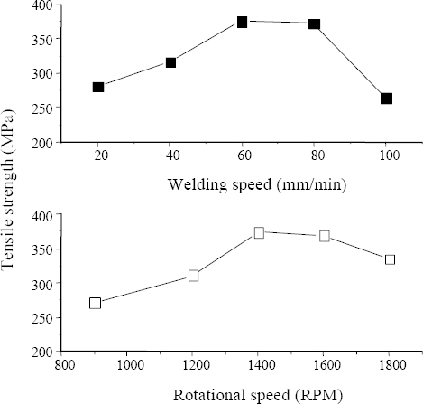
The published research into FSW of aluminum alloys over the last ten years was reviewed and is summarized in Fig. 8. Studies of FSW welding have steadily increased in last decade, especially within the last five years. Research into the use of FSW for high strength Al 7075 has been conducted both in Korea and abroad. The 2XXX and 7XXX series aluminum alloys are well known to have narrow process window compared with other aluminum alloys43). These FSW process parameters, such as tool rotation speed, welding speed, and tool shape, affect the physical properties of the resulting welds. Therefore, the design of the welding tool and the selection of the process parameters are very important factors in FSW. Rajakumar et al. state that the strength and hardness of welds produced by FSW vary depending on the process conditions, as shown in Fig. 929,30). Rajakumar et al. also reported a tensile fracture strength of about 350 MPa, but a strength in excess of 480 MPa was achieved in other reviewed literature14,16,29,30,37). This indicates that a large variation in strength may occur, even when applying a solid-state welding process like FSW.

Fig. 8

Published technical papers discussing friction stir welding over the last 10 years

Fig. 9

Variation in the tensile strength of FSW-welded specimens according to welding speed (Rotational speed = 1400 rpm, Force = 8 kN) and rotational speed (Welding speed = 60 mm/s, Force = 8 kN)29,30)

The welds produced by FSW can be divided into a stir zone (SZ), a thermomechanically affected zone (TMAZ), an HAZ, and the BM. In some cases in the literature, the TMAZ is further subdivided by the presence of recrystallization34). As shown in Fig. 10, the lowest hardness across the weld profile was measured in the heat affected zone17,23). This can be explained by the precipitation and recrystallization behavior. Su et al. applied FSW to an Al 7050-T651 alloy, and investigated the behavior of the precipitate using a transmission electron microscope (TEM). Fine spherical precipitates with a diameter of about 50 μm were found to be uniformly distributed in the BM. In the TMAZ, precipitates of 10 to 100 μm in size were found to be elongated along the grain boundaries. In the HAZ, increased precipitation was observed, particularly at the grain boundary due to the heat generated during the FSW process. It was confirmed that thermal softening had occurred in this region. Within the SZ, dynamic recrystallization was observed to occur. Equiaxed grains formed during the recrystallization process, but hardness degradation was not severe as typically observed hardness in the FZ of fusion welds. The reason for this can be explained by Su et al.’s observation of the sub-grain formation and dislocation within the grain22,24,32,34,44). The location of tensile fracture in welds created by FSW was observed in the HAZ, at a higher strength than that obtained by fusion welding.

Fig. 10

Effect of welding speed on the microhardness of an Al 7075-T6 aluminum alloy welded under constant rotational speed (1400 rpm) and force (8 kN)30)

Fig. 11

Grain structure of different weld regions: (a) base metal, (b) dark field image of base metal region, (c) HAZ, (d)-(e) TMAZ, and (f) SZ34)

Fig. 12

Light optical macrographs showing the location and appearance of fracture in a dissimilar friction stir weldment SSRT tested in a 3.5% NaCl solution (nominal strain rate 10-7 s-1): (a) photograph of failed specimen showing the extent of pitting and damage; (b) micrograph revealing the precise fracture location11)

However, FSW is limited in process flexibility than fusion welding. Additionally, the process speed of FSW is even lower than that of arc welding. Although the FSW process has been mentioned as one of the possible candidates to replace the conventional fusion welding process, it has not yet been widely applied in many industrial fields for these reasons.

5. Conclusions

The 7XXX series aluminum alloys are considered to be a key material in the next generation of automobile bodies due to their high stiffness and relatively moderate price. However, traditional fusion welding processes are difficult to apply to these alloys because of their high thermal conductivity and thermal expansion coefficient. Additionally, the low vaporization temperature of alloying elements results in a wide mush zone, which makes the application of conventional fusion welding processes problematic.

An optimized process for welding 7XXX series aluminum alloys has yet to be established. As a result, the degradation of the properties of the heat affected zone resulting from thermal softening, which occurs regardless of the welding process, has yet to be mitigated.

Higher tensile strength can be obtained in welds created by the laser welding or friction stir welding processes than with arc welding. The hardness of the fusion zone was not observed to improve after the age hardening treatment, and the properties of the heat affected zone were observed to deteriorate regardless of the welding process, suggesting a limit to the enhancement of joint strength using any current welding process.

Nevertheless, the use of aluminum alloys in the global automobile market is becoming competitive as lightweight car body technology is increasingly required to satisfy the requirements of both safety regulations and fuel efficiency. The use of 7XXX aluminum alloys is destined to increase in the automobile industry, and technical preparations must be undertaken to ensure that the necessary welding and joining can be conducted successfully and cost-effectively in order to respond to the rapidly changing needs of the automobile customer.

References

1. Lutsey N. P. Review of technical literature and trends related to automobile mass-reduction technology. Institute of Transportation Studies 2010;
2. Zhao H, White D. R, Debroy T. Current issues and problems in laser welding of automotive aluminium alloys. International Materials Reviews 44(6)1999;:238–266. http://dx.doi.org/10.1179/095066099101528298.
3. Inaba T, Tokuda K, Yamashita H, Takebayashi Y, Minoura T, Sasabe S. Wrought aluminum technologies for automobiles. Kobelco Technology Review 262005;:55–62.
4. Dursun T, Soutis C. Recent developments in advanced aircraft aluminium alloys. Materials & Design 562014;:862–871. https://doi.org/10.1016/j.matdes.2013.12.002.
5. Hirsch J. Recent development in aluminium for automotive applications. Transactions of Nonferrous Metals Society of China 24(7)2014;:1995–2002. https://doi.org/10.1016/S1003-6326(14)63305-7.
6. Zhou J, Wan X, Li Y. Advanced aluminium products and manufacturing technologies applied on vehicles presented at the EuroCarBody conference. Materials Today, Proceedings 2(10)2015;:5015–5022. https://doi.org/10.1016/j.matpr.2015.10.091.
7. Shin J, Kim T, Kim D, Kim D, Kim K. Castability and mechanical properties of new 7xxx aluminum alloys for automotive chassis/body applications. Journal of Alloys and Compounds 6982017;:577–590. https://doi.org/10.1016/j.jallcom.2016.12.269.
8. Lee M, Jung S.-H. Trends of advanced multi-material technology for light materials based on aluminum. Journal of Welding and Joining 34(5)2016;:19–25. https://doi.org/10.5781/JWJ.2016.34.5.19.
9. Kumar A, Milton M. S. A Comparison of welding techniques of aluminium alloys, A literature review. International Journal of Scientific Research in Science, Engineering and Technology 2(3)2016;:172–175.
10. Rajan R, Kah P, Mvola B, Martikainen J. Trends in aluminium alloy development and their joining methods. Reviews on Advanced Materials Science 44(4)2016;:383–397.
11. Srinivasan P. B, Dietzel W, Zettler R, Dos Santos J, Sivan V. Stress corrosion cracking susceptibility of friction stir welded AA7075–AA6056 dissimilar joint. Materials Science and Engineering, A 392(1)2005;:292–300. https://doi.org/10.1016/j.msea.2004.09.065.
12. Balasubramanian V, Ravisankar V, Reddy G. M. Effect of pulsed current and post weld aging treatment on tensile properties of argon arc welded high strength aluminium alloy. Materials Science and Engineering, A 459(1–2)2007;:19–34. https://doi.org/10.1016/j.msea.2006.12.125.
13. Cavaliere P, Nobile R, Panella F, Squillace A. Mechanical and microstructural behaviour of 2024–7075 aluminium alloy sheets joined by friction stir welding. International Journal of Machine Tools and Manufacture 46(6)2006;:588–594. https://doi.org/10.1016/j.ijmachtools.2005.07.010.
14. Chao Y, Wang Y, Miller K. Effect of friction stir welding on dynamic properties of AA2024-T3 and AA7075- T7351. Welding journal 80(8)2001;:196–200.
15. Charit I, Mishra R. S, Mahoney M. W. Multi-sheet structures in 7475 aluminum by friction stir welding in concert with post-weld superplastic forming. Scripta Materialia 47(9)2002;:631–636. https://doi.org/10.1016/S1359-6462(02)00257-9.
16. Da Silva A, Arruti E, Janeiro G, Aldanondo E, Alvarez P, Echeverria A. Material flow and mechanical behaviour of dissimilar AA2024-T3 and AA7075- T6 aluminium alloys friction stir welds. Materials & Design 32(4)2011;:2021–2027. https://doi.org/10.1016/j.matdes.2010.11.059.
17. Fratini L, Buffa G, Shivpuri R. Mechanical and metallurgical effects of in process cooling during friction stir welding of AA7075-T6 butt joints. Acta Materialia 58(6)2010;:2056–2067. https://doi.org/10.1016/j.actamat.2009.11.048.
18. Hu B, Richardson I. Hybrid laser/GMA welding aluminium alloy 7075. Welding in the World 50(7-8)2006;:51–57. https://doi.org/10.1007/BF03266536.
19. Hu B, Richardson I. M. Mechanism and possible solution for transverse solidification cracking in laser welding of high strength aluminium alloys. Materials Science and Engineering, A 429(1–2)2006;:287–294. https://doi.org//10.1016/j.msea.2006.05.040.
20. Hu B, Richardson I. M. Microstructure and mechanical properties of AA7075(T6) hybrid laser/GMA welds. Materials Science and Engineering, A 459(1–2)2007;:94–100. https://doi.org/10.1016/j.msea.2006.12.094.
21. Hwang R, Chou C. The study on microstructural and mechanical properties of weld heat affected zone of 7075-T651 aluminum alloy. Scripta Materialia 38(2)1997;:215–221. https://doi.org/10.1016/S1359-6462(97)00472-7.
22. Jata K, Sankaran K, Ruschau J. Friction-stir welding effects on microstructure and fatigue of aluminum alloy 7050-T7451. Materials Science and Engineering, A 31(9)2000;:2181–2192. https://doi.org/10.1007/s11661-000-0136-9.
23. Khodir S. A, Shibayanagi T. Friction stir welding of dissimilar AA2024 and AA7075 aluminum alloys. Materials Science and Engineering, B 148(1)2008;:82–87. https://doi.org/10.1016/j.mseb.2007.09.024.
24. Ma Z. Y, Mishra R. S, Mahoney M. W. Superplastic deformation behaviour of friction stir processed 7075Al alloy. Acta Materialia 50(17)2002;:4419–4430. https://doi.org/10.1016/S1359-6454(02)00278-1.
25. Ola O, Doern F. Fusion weldability studies in aerospace AA7075-T651 using high-power continuous wave laser beam techniques. Materials & Design 772015;:50–58. https://doi.org/10.1016/j.matdes.2015.03.064.
26. Paleocrassas A, Tu J. Low-speed laser welding of aluminum alloy 7075-T6 using a 300-W, single-mode, ytterbium fiber laser. Welding Journal-New York 86(6)2007;:179–186.
27. Paleocrassas A. G, Tu J. F. Inherent instability investigation for low speed laser welding of aluminum using a single-mode fiber laser. Journal of Materials Processing Technology 210(10)2010;:1411–1418. https://doi.org/10.1016/j.jmatprotec.2010.04.002.
28. Rafi H. K, Ram G. J, Phanikumar G, Rao K. P. Microstructure and tensile properties of friction welded aluminum alloy AA7075-T6. Materials & Design (1980-2015) 31(5)2010;:2375–2380. https://doi.org/10.1016/j.matdes.2009.11.065.
29. Rajakumar S, Muralidharan C, Balasubramanian V. Optimization of the friction-stir-welding process and tool parameters to attain a maximum tensile strength of AA7075-T6 aluminium alloy. Proceedings of the Institution of Mechanical Engineers, Part B, Journal of Engineering Manufacture 224(8)2010;:1175–1191. https://doi.org/10.1243/09544054JEM1802.
30. Rajakumar S, Muralidharan C, Balasubramanian V. Influence of friction stir welding process and tool parameters on strength properties of AA7075-T6 aluminium alloy joints. Materials & Design 32(2)2011;:535–549. https://doi.org/10.1016/j.matdes.2010.08.025.
31. Ravindra B, Kumar T. S, Balasubramanian V. Fatigue life prediction of gas metal arc welded crucifrom joints of AA7075 aluminium alloy failing from root region. Transactions of Nonferrous Metals Society of China 21(6)2011;:1210–1217. https://doi.org/10.1016/S1003-6326(11)60844-3.
32. Rhodes C, Mahoney M, Bingel W, Calabrese M. Fine-grain evolution in friction-stir processed 7050 aluminum. Scripta Materialia 48(10)2003;:1451–1455. https://doi.org/10.1016/S1359-6462(03)00082-4.
33. Sivashanmugam M, Kumar T, Shanmugam C. J, Sathishkumar M. Investigation of microstructure and mechanical properties of GTAW and GMAW joints on AA7075 aluminum alloy. Frontiers in Automobile and Mechanical Engineering 2010;:241–246. https://doi.org/10.1109/FAME.2010.5714843.
34. Su J. Q, Nelson T. W, Mishra R, Mahoney M. Microstructural investigation of friction stir welded 7050-T651 aluminium. Acta Materialia 51(3)2003;:713–729. http://dx.doi.org/10.1016/S1359-6454(02)00449-4.
35. Temmar M, Hadji M, Sahraoui T. Effect of post-weld aging treatment on mechanical properties of tungsten inert gas welded low thickness 7075 aluminium alloy joints. Materials & Design 32(6)2011;:3532–3536. https://doi.org/10.1016/j.matdes.2011.02.011.
36. Tu J, Paleocrassas A. Fatigue crack fusion in thin- sheet aluminum alloys AA7075-T6 using low-speed fiber laser welding. Journal of Materials Processing Technology 211(1)2011;:95–102. https://doi.org/10.1016/j.jmatprotec.2010.09.001.
37. Widener C. A, Franklin J, Jasthi B. K, West M. K. Mechancial properties of repaired 7075-T73 friction stir weld butt welds Springer; 2013. p. 205–213. https://doi.org/10.1007/978-3-319-48108-1_21.
38. Zhang D, Zhao Z, Gao S, Zhao H. Research on CO2laser welding with filler wire of dissimilar high strength aluminum alloy 2024 and 7075. Photonics and Optoelectronics 2012;:1–4. https://doi.org/10.1109/SOPO.2012.6270445.
39. Liu C, Northwood D. O, Bhole S. D. Tensile fracture behavior in CO2 laser beam welds of 7075-T6 aluminum alloy. Materials & Design 25(7)2004;:573–577. http://dx.doi.org/10.1016/j.matdes.2004.02.017.
40. Mathers G. The welding of aluminium and its alloys Woodhead publishing; 2002. p. 43–50. https://doi.org/10.1533/9781855737631.
41. He Z.-B, Peng Y.-Y, Yin Z.-M, Lei X.-F. Comparison of FSW and TIG welded joints in Al-Mg-Mn-Sc-Zr alloy plates. Transactions of Nonferrous Metals Society of China 21(8)2011;:1685–1691. https://doi.org/10.1016/S1003-6326(11)60915-1.
42. Mishra R. S, Ma Z. Y. Friction stir welding and processing. Materials Science and Engineering, R:Reports 50(1)2005;:1–78. https://doi.org/10.1016/j.mser.2005.07.001.
43. Kim C. O, Kim S. J. Effect of welding condition on tensile properties of friction stir welded joints of Al- 7075-T651 plate. Journal of the Korea Society For Power System Engineering 15(2)2011;:61–68. https://doi.org/10.9726/kspse.2011.15.2.061.
44. Jata K, Semiatin S. Continuous dynamic recrystallization during friction stir welding of high strength aluminum alloys. Scripta Materialia 432000;:743–749. https://doi.org/10.1016/S1359-6462(00)00480-2.

Article information Continued

Table 1

Weldability of various aluminum alloys10)

1XXX 2XXX 3XXX 4XXX 5XXX 6XXX 7XXX 8XXX
Traditional welding + - + + + + - +/-
Friction stir welding + + + + + + + +

Note: “-” indicates “mostly non-weldable”; “+” indicates “mostly weldable”

Table 2

Research into the welding and joining of 7XXX series aluminum alloys over the last ten years

Welding process Date Authors Materials Filler materials
Heat treatment 1997 Hwang et al.21) 7075-T651 -
GTAW, GMAW 2007 Balasubramanian et al.12) 7075 5356
GMAW 2010 Sivashanmugam et al.33) 7075 4043
GMAW 2011 Ravindra et al.31) 7075-T6 5356
GTAW 2011 Temmar et al.35) 7075-T6 -
L-A hybrid 2006 Hu et al.18) 7075-T6 5754
L-A hybrid 2006 Hu et al.19) 7075-T6, 2024-T3 5754
L-A hybrid 2007 Hu et al.20) 7075-T6 5754, 2319
LBW 2004 Liu et al.39) 7075-T6 -
LBW 2007 Paleocrassas et al.26) 7075-T6 -
LBW 2010 Paleocrassas et al.27) 7075-T6 -
LBW 2011 Tu et al.36) 7075-T6 -
LBW 2012 Zhang et al.38) 7075-T6, 2024-T351 4043, 2319
LBW 2015 Ola et al.25) 7075-T651 4043
FSW 2000 Jata et al.22) 7050-T7451 -
FSW 2001 Chao et al.14) 7075-T7351, 2024-T3 -
FSW 2002 Charit et al.15) 7475 -
FSW 2002 Ma et al.24) 7075 -
FSW 2003 Rhodes et al.32) 7050-T76 -
FSW 2003 Su et al.34) 7050-T651 -
FSW-D 2005 Srinivasan et al.11) 7075-T7351, 6056 -
FSW 2006 Cavaliere et al.13) 7075-T6, 2024-T3 -
FSW 2008 Khodir et al.23) 7075-T6, 2024-T3 -
FSW 2010 Rafi et al.28) 7075-T6 -
FSW 2010 Rajakumar et al.29) 7075-T6 -
FSW 2011 Rajakumar et al.30) 7075-T6 -
FSW 2010 Fratini et al.17) 7075-T6 -
FSW 2011 Silva et al.16) 7075-T6, 2024-T3 -
FSW 2013 Widener et al.37) 7050-T73 -

Note: “L-A hybrid” indicates “laser-arc hybrid”; “LBW” indicates “laser beam welding”; “FSW” indicates “friction stir welding”; “FSW-D” in indicates “friction stir welding with dissimilar materials”

Table 3

General guidance on filler metal selection modified from reference40)

Parent metal 1XXX 2XXX 3XXX 4XXX 5XXX 6XXX 7XXX
1XXX 1XXX 4XXX NR 3XXX 4XXX 1XXX 4XXX 5XXX 4XXX 5XXX
2XXX NR NR NR 4047 NR NR NR
3XXX 3XXX 4XXX NR 4XXX 3XXX 4XXX 5XXX 5XXX 5XXX
4XXX 1XXX 4XXX 4047 3XXX 4XXX 4XXX NR 4XXX 5XXX 4XXX 5XXX
5XXX 5XXX NR 5XXX NR 5XXX 5XXX 5XXX
6XXX 4XXX NR 5XXX 4XXX 5XXX 5XXX 4XXX 5XXX 5XXX
7XXX 5XXX NR 5XXX 4XXX 5XXX 5XXX 5XXX 5XXX

Note: “NR” indicates “not recommended”

Fig. 1

Optical micrographs of as-welded joints: (a) base metal, (b) fusion zone, (c) heat affected zone, (d) columnar grain at the partially melted zone, and (e) incipient melting at the partially melted zone33,35)

Table 4

Vickers hardness and tensile strength of arc welded specimens without post aging12,35,39)

Study (Heat input per length) Hardness (Hv) Strength (MPa) Efficiency (%) Process
WM PMAZ HAZ BM
Balasubramanian et al. (4 kJ/mm) 70 80 95 136 235 45.2 GMAW
Balasubramanian et al. (3 kJ/mm) 80 90 104 138 254 45.8 GMAW
Temmar et al. 85.4 - 107.1 137.9 248 48.8 GMAW
Balasubramanian et al. (3 kJ/mm) 85 100 116 140 272 52.3 GTAW
Balasubramanian et al. (2 kJ/mm) 100 110 122 142 295 56.7 GTAW
Liu et al. (2.2 kJ/mm) - - - - 432 71.0 GTAW
Average 84.1 95.0 108.8 138.8 289.5 58.5
Standard Deviation 9.70 11.18 9.41 2.05 66.86 13.96

Table 5

Vickers hardness and tensile strength of arc welded specimens with artificial aging12,35,39)

Study (Heat input per length) Hardness (Hv) Strength (MPa) Efficiency (%) Process Remarks
WM PMAZ HAZ BM
Balasubramanian et al. (4 kJ/mm) 85 90 96 138 251 48.3 GMAW 125 °C 24 h
Balasubramanian et al. (3 kJ/mm) 96 100 105 140 270 51.9 GMAW 125 °C 24 h
Temmar et al. 101.2 - 120.6 140.5 268 52.8 GMAW 140 °C 10 h
Balasubramanian et al. (3 kJ/mm) 105 100 116 142 292 56.2 GTAW 125 °C 24 h
Balasubramanian et al. (2 kJ/mm) 115 120 124 145 314 60.4 GTAW 125 °C 24 h
Liu et al. (2.2 kJ/mm) - - - - 455.5 74.7 GTAW 120 °C 26 h
Average 100.4 102.5 112.3 141.1 308.4 59.3
Standard deviation 9.91 10.90 10.39 2.33 68.73 14.35

Fig. 2

Macro-section images of the transverse weld produced by (a) autogenous laser welding and (b) laser/GMAW hybrid welding20)

Fig. 3

Weld defects (a) transverse cracking on the top bead of an Al7075 laser-arc hybrid welded sample, (b) a typical HAZ crack in laser welded Al7075 (c) X-ray radiography showing the extent of porosity in laser-arc hybrid welded Al7075-T651, and (d) X-ray radiography of laser welds supplied with 4043 cold wire18,19,25)

Fig. 4

The length of intergranular cracking in the HAZ under various welding process (modified from reference)25) (Note: “LBW” indicates “laser beam welding”; “CW” indicates “cold wire”; “L-A” indicates “laser-arc”; “BH” indicates “base metal preheating by laser”)

Fig. 5

Tensile strengths of 7075-T6 base metal and as- welded specimens under different aging conditions, (modified from reference)18-20,39) (Note: “LH” indicates “low heat input”; “HH” indicates “high heat input”)

Fig. 6

The transverse micro-hardness profile of laser welds made at a welding speed of 80 mm/s (modified from reference)18,20)

Fig. 7

Image showing the microstructure of a laser- GMAW hybrid weld on an Al7075 alloy. The weld was made with an Al5754 filler wire at a welding speed of 80 mm/s20)

Fig. 8

Published technical papers discussing friction stir welding over the last 10 years

Fig. 9

Variation in the tensile strength of FSW-welded specimens according to welding speed (Rotational speed = 1400 rpm, Force = 8 kN) and rotational speed (Welding speed = 60 mm/s, Force = 8 kN)29,30)

Fig. 10

Effect of welding speed on the microhardness of an Al 7075-T6 aluminum alloy welded under constant rotational speed (1400 rpm) and force (8 kN)30)

Fig. 11

Grain structure of different weld regions: (a) base metal, (b) dark field image of base metal region, (c) HAZ, (d)-(e) TMAZ, and (f) SZ34)

Fig. 12

Light optical macrographs showing the location and appearance of fracture in a dissimilar friction stir weldment SSRT tested in a 3.5% NaCl solution (nominal strain rate 10-7 s-1): (a) photograph of failed specimen showing the extent of pitting and damage; (b) micrograph revealing the precise fracture location11)