


Fatigue Crack Growth Evaluation of IMO Type B Spherical LNG Cargo Tank Considering the Effect of Stress Ratio and Load History
Stress Ratio 및 Load History 효과를 고려한 IMO Type B Spherical LNG Cargo Tank 피로 균열진전 평가
-
Myung-Sup Lee*,**
 , Myung-Hyun Kim*,†
- Received July 30, 2021 Revised August 30, 2021 Accepted September 27, 2021
- ABSTRACT
-
The crack propagation on a spherical IMO Type B LNG tank deployed on a 150K class LNG carrier is studied. IMO Type B tanks require a high level of safety . Therefore, analyses such as strength evaluation, fatigue analysis, fatigue crack propagation analysis, and LNG leak rate should be conducted to ensure safety. Various fatigue crack growth models were proposed for fatigue crack propagation analysis. The Forman model and the Walker model consider the stress ratio. Furthermore, the Huang model, and the Lee and Kim model consider the stress ratio and the effects of overload and underload present in the past load history on crack propagation.To examine the effects of stress ratio and load history for the fatigue crack propagation models, the crack growth of the LNG tank was evaluated by considering the stresses under full load and ballast load operating conditions, and three stress amplitude sequence cases.
- 1. Introduction
- 1. Introduction
Owing to recent environmental problems, natural gas has attracted much attention as eco-friendly fuel in the intermediate stage of conversion into green energy sources, such as hydrogen and ammonia, which can reduce the emission of sulfur oxides, nitrogen oxides, and carbon dioxide. Natural gas is transported as liquefied natural gas (LNG) that can reduce the volume to 1/600 to improve transport efficiency. For the liquefaction of natural gas, it is maintained at -163℃ under the atmospheric pressure. To transport such cryogenic and dangerous cargo, LNG cargo holds must be designed in accordance with IMO IGC Code1).IMO classifies cargo holds mainly into independent and integrated tanks according to the connection with the hull structure as shown in Fig. 1. Independent tanks are again divided into Type A, B, and C tanks according to the type of the secondary barrier that can store LNG for 15 days of movement to a nearby port when the primary barrier is damaged during a voyage. The Type B tank, which is the target of this study, will be described later. In the case of the Type A tank, it must be equipped with a full secondary barrier. The hull structure that surrounds the tank is utilized as the secondary barrier and must be built using materials that can withstand low temperatures. The Type A tank is usually applied to vessels whose hulls are exposed to relatively high temperatures (-55℃), such as liquefied petroleum gas (LPG) carriers. In the case of the Type C tank, high safety must be secured through an increase in design pressure as well as internal pressure and non- destructive tests in the production stage so that no secondary barrier is required. To withstand high pressure, cylindrical or Bi-Lobe type pressure vessels are commonly used. Integrated tanks are directly connected to the hull structure (Mastic Bonding). They consist of membrane-type primary and secondary barriers to withstand the hull behavior and internal LNG load, and GTT’s Mark III and NO96 systems are commonly used.The Type B tank, which is the target of this study, is equipped with a partial secondary barrier that is referred to as a drip tray. The partial secondary barrier is allowed for the Type B tank because the “leak before failure” concept is applied through the extensive analysis of the tank2,3). In other words, the Type B tank must not be subjected to fatigue failure through fatigue analysis and fatigue crack growth (FCG) analysis. Even if a fatigue crack occurs, the LNG leaked through the fatigue crack must be collected in the drip tray through the leakage path between the tank and the insulation material, and the drip tray must be designed in a size that can store the leaked LNG for 15 days to secure the safety of the vessel. The Type B tank has been used for LNG carriers and as the LNG fuel tank as it does not exhibit the sloshing problem that occurs during the partial filling of cargo along with high strength and reliability4).In this study, research was conducted on the crack growth of Type B spherical tanks, which have been built in large quantities in South Korea. The effects of the stress ratio and load history were examined using various crack growth analysis models.

- 2. LNG Tank Strength Evaluation
- 2. LNG Tank Strength Evaluation
- 2.1 Overview of 150K-class LNG carrier
- 2.1 Overview of 150K-class LNG carrier
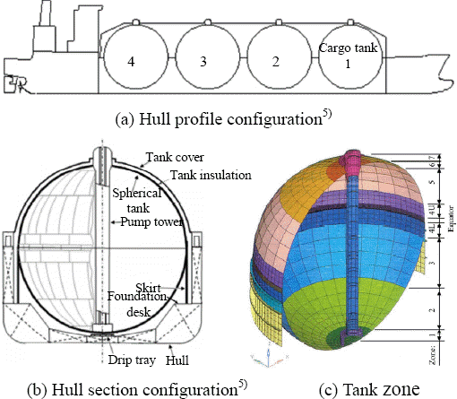
In the LNG carrier, four cargo tanks in the same size are arranged as shown in Fig. 2. Each cargo tank consists of a tank insulation panel that surrounds the tank, a tank cover that surrounds the tank and insulation material, a pump tower in which an LNG pump and pipelines are installed, a skirt and a foundation desk that connect the equator of the tank to the hull, and a drip tray that collects the leaked LNG. Each tank has eight zones with different thicknesses, including the equator, depending on the vertical location.- 2.2 LNG tank strength evaluation procedure
- 2.2 LNG tank strength evaluation procedure
The tank strength must be evaluated first to calculate the stress to be applied to the crack growth of the spherical LNG tank, and several analysis procedures are required. First, the wave load and the acceleration of each tank are calculated through hydrodynamic analysis under various cargo loading conditions and applied to the structural analysis of the tank. Loads that are applied to the structural analysis include static/dynamic loads by loaded cargo including LNG and the weight of the hull, internal/external vapor pressures, thermal distribution and thermal stress by the temperature difference between cryogenic LNG and the outside air at room temperature, and the hull interaction load. Once the thickness of the tank is determined through yield and buckling strength evaluation, the size of the drip tray is determined by calculating the LNG leak rate after conducting fine mesh analysis for the tank, skirt, or pump tower joints; buckling strength evaluation for the skirt; pump tower strength evaluation in consideration of sloshing; fatigue analysis for evaluating initial cracking; and crack growth analysis for calculating the crack growth rate2). Fig. 3 shows the full ship finite element analysis (FEA) model used for analysis and the shape of the cargo hold deformed by the hull girder bending moment.

- 3. FCG Analysis and Model Comparison
- 3. FCG Analysis and Model Comparison
- 3.1 FCG
- 3.1 FCG
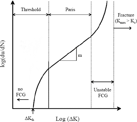
In general, the Paris model shown in equation (1) is used to evaluate the crack growth behavior, which is expressed using the relationship between the stress intensity factor (ΔK) and the crack growth rate (da/dN) as shown in Fig. 4.where a is the crack size, N is the number of loads, and C and m are material constants.Classification societies, such as LR2) and DNV3), follow British Standard BS79107) to calculate the stress intensity factor (ΔK) as shown in equation (2). BS7910 uses the Newman-Raju method8) that considers the combination of the membrane stress and bending stress to calculate YΔσ of the elliptical surface defect as shown in equation (3).where Y is the shape function, Δσis the stress amplitude, Δσm is the membrane stress amplitude, Δσb is the bending stress amplitude, Mkm and Mkb are the membrane and bending stress concentration factors at the weld toe, H is the ratio between the membrane and bending stress concentration factors, F is a function of the crack geometry and thickness, and φ is the elliptic function for crack geometry7).- 3.2 FCG models
- 3.2 FCG models
Since the Paris model cannot reflect the actual crack growth as it does not consider various stress ratios and load history that are applied to the actual structure, various crack growth models have been proposed.First, models that consider the stress ratio (R), which represents the ratio between the maximum and minimum stresses, are as follows9). Walker10), Eason et al.11), and Kurihara et al.12) expressed the stress ratio in the form of ∆Keff=f(R)∆K orwhere r is the material constant.Forman13) and McEvily and Gregor14) added the fracture toughness (KC) or the maximum stress intensity factor (Kmax) to the Paris model as shown in equation (5)9). The second equation shows that the crack growth rate increases as the Kmax value approaches Kc15).Huang and Moan16) proposed a model by adjusting various stress intensity factor values that occurred in test results with different stress ratios using the test results of R=0 as shown in equation (6), and a model that considers both the stress ratio correction factor (MR) and the plastic region size correction factor (MP), which explains the delay in crack growth by overload, as shown in equation (7)17).Lee and Kim18) introduced the load history correction factor (MH) that can consider underload as well as overload using Port’s empirical formula19) based on the Huang model as shown in equation (11) and proposed a crack growth model as shown in equation (8). This model applied exponential weights for the stress ratio correction factor (MR) and load history correction factor (MH) by comparing various tests that could be found in the literature as shown in equations (9) to (11).where,R1 = Stress ratioβ = 0.5 for titanium alloy = 0.7 for aluminum alloys and steels β1=1.2βKOL, KUL, Kmax : Stress intensity factor for overload, underload and maximum load- 3.3 FCG analysis for the spherical LNG tank
- 3.3 FCG analysis for the spherical LNG tank
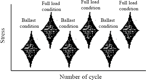
Fig. 5 shows the stress amplitudes and positions applied in crack grown evaluation through the LNG tank strength evaluation described above. The membrane and bending stress amplitudes in the weld zone between Zone 2 and Zone 3, which had a relatively high stress amplitude and a wide range, were evaluated to be 40 and 2.5 MPa, respectively. In addition, the static stresses under the full load and ballast operating conditions were calculated to be 42.5 and 2.0 MPa, respectively. Fig. 6 shows a schematic diagram for the stress history applied to the vessel.As for the size of the initial surface defect, a depth (a) of 0.5 mm and a length (2c) of 50 mm were applied in accordance with the non-destructive testing (NDT) acceptable standards of a shipyard20).Table 2 shows the crack growth-related material properties of the aluminum alloy (5083-O) used to build the tank.Table 2
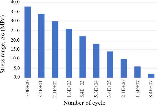
Material property for AL5083-OC (mm/cycle) m (MPa √mm) Kth (MPa mm3/2) 1.536E-1221) 3.0421) 24.322) The stress intensity factor (ΔK) can be calculated using an empirical formula obtained through tests23) and an analytical method24), but it was calculated in this study using equation (3) according to BS79107) Annex M for a surface defect as shown in Fig. 7. In addition, the stress concentration factor according to the construction tolerance of LR Procedure2) Section D12 was considered.In this study, the membrane stress distribution shown in Fig. 8 was applied by assuming the long term wave- induced stress range spectrum that encounters the North Atlantic wave 108 times and 1.0 for the Weibull distribution shape function, h, in accordance with the DNV Guideline3). In addition, the cases of exposure to three stress amplitude sequences during a one-way trip were evaluated to examine the influence of the change in load history on crack growth as shown in Fig. 9. For Case 1, a general distribution in which small loads are applied in coastal waters and large loads in the distant sea during operation was assumed. For Case 2 and Case 3, the load increased or decreased during operation. Under the condition of performing 500 voyages during the service life of the vessel, the stress distribution of one voyage was assumed to be 2 × 10⁵ cycles.


- 4. Results and Discussion
- 4. Results and Discussion
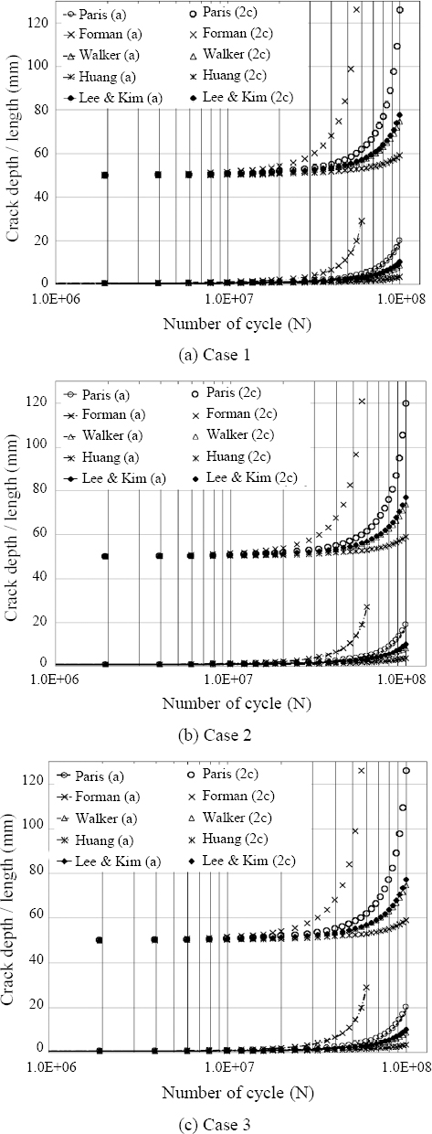
Fig. 10 shows the results of applying five crack growth models and three load histories to the IMP Type B spherical LNG tank. In the Forman model, the crack depth “a” exceeded 22.5 mm, which corresponds to the crack depth criterion of 0.5 t at 6.0E+07 cycles. Overall, the Forman and Paris models exhibited conservative results while the Huang model showed the most optimistic results. The Lee & Kim model exhibited relatively optimistic results in a similar manner to the Walker model. The Forman and Walker models consider the stress ratio as shown in equations (4) and (5). In the case of the Walker model, the crack growth rate according to the increase in stress ratio was evaluated to be slower compared to the Forman model because m is used as an exponent for the stress ratio.Fig. 11 shows the detailed results of crack growth for 1.0E+6 to 1.0E+7 cycles in Case 1. All models, except for the Paris model, exhibited stepwise increases in crack growth rate as the number of cycles increased. This indicates an increase in crack growth rate under the full load condition and a reduction in crack growth rate under the ballast operating condition. Meanwhile, the Huang model and the Lee & Kim model, which consider both the stress ratio and load history, clearly show the process in which crack growth is accelerated under the full load condition and decelerated under the ballast operating condition25). In the case of the Huang model, the lowest crack growth rate was observed as shown in Fig. 11 because the weakening of the cracking delay by overload26,27) cannot be reflected when underload is applied after overload in the past load history unlike the Lee & Kim model.To compare the influence of the three load history cases, the crack growth results for each model are shown in Fig. 12. The Paris, Forman, and Walker models showed no significant difference despite the difference among the three load history cases. In the Huang model that considered the plastic region size correction factor(MP) and the Lee & Kim model that introduced the load history correction factor (MH), the slowest crack growth was observed in Case 3 where the load continuously decreased during operation and the highest crack growth rate in Case 2. The crack growth rate varies depending on the probability of the occurrence of overload in the past. For Case 3, the delay in crack growth continuously occurs because overload is always present in the load history.


- 5. Conclusion
- 5. Conclusion
1) The Paris model that shows conservative results does not consider the stress ratio and load history, and it has been used in actual ship design through the rules of classification societies and international standards.
2) The Forman and Walker model that consider the stress ratio generally show conservative results, but the results are different depending on the method of applying the stress ratio. Neither of them considers the effect of the load history.
3) The Huang model reflects a reasonable stress ratio, but shows optimistic results because it cannot reflect the reduction in the crack growth delay of overload by underload.
4) The Lee & Kim model is applicable in actual design because it considers the load history by underload as well as overload and shows results close to those of the Paris model.
In this study, research was conducted on the crack growth of the IMP Type B spherical LNG tank placed in a 150K-class liquefied natural gas (LNG) carrier. The effects of the stress ratio and load history were examine using various crack growth analysis models.In the case of the IMO Type B tank, fatigue analysis, fatigue crack growth (FCG) analysis, and the calculation of the LNG leak rate are necessary in addition to strength evaluation because a high level of safety is required through various analyses. Various models other than the Paris model have been proposed for FCG analysis. The Forman and Walker models consider the stress ratio, whereas the Huang model and the Lee & Kim model consider the influence of the presence of overload and underload in the past load history on crack growth as well as the stress ratio.The FCG of the LNG tank was evaluated considering the stress under full load and ballast operating conditions and three stress amplitude sequence cases to examine the effects of the stress ratio and load history for five crack growth models, and the following conclusions were drawn.
- REFERENCES
- REFERENCES
- 1. IMO. The International Code of the Construction and Equipment of Ships Carrying Liquefied Gases in Bulk (IGC Code), Imternational Maritime Organizqation Resolution MSC. 370(93) (2014)2. LR. Fatigue assessment of ship units adopting IMO Type B independent tanks constructed primarily of plane surfaces for the storage of liquefied gases, Lloyd's Register ShipRight Design and construction. (2014)3. DNV GL, Liquefied gas carriers with spherical tanks of type B, DNV GL DNVGL-CG-0134. (2018)4. Y. Nagata, IHI-SPB Tank for LNG-Fueled Ship, IHI Engineering Review. 2 (2015)5. U. N. Kim, A Study on the Buckling Strength of the Skirt Structure in the Spherical LNG Carriers, J. Soc. Naval Archit. Korea. 54 (2017) 393–405. https://doi.org/10.3744/SNAK.2017.54.5.393
[Article]6. J. A. Newman, The Effects of Load Ratio on Threshold Fatigue Crack Growth of Aluminum Alloys, Virginiatech Doctor Dissertation. (2000)7. BS7910. Guide to methods for assessing the acceptability of flaws in metallic structures, British Standards. (2013)8. J. C. Newman Jr and I. S. Faju, Analyses of surface cracks in finite plates under tension or bending loads, NASA Technical Report. 1578 (1979)9. A. Chahardehi and A. Mehmanparast, Fatigue crack growth under remote and local compression - a state-of- the-art review, Frattura ed IntegritàStrutturale. 35 (2016) 41–49. https://doi.org/10.3221/IGF-ESIS.35.05
[Article]10. K. Walker, The effect of stress ratio during crack propagation and fatigue for 2024-T3 and 7075-T6 aluminum, ASTM STP462. (1970)
[Article]11. E. D. Eason, J. D. Gilman, D. P. Jones, and S. P. Andrew, Technical basis for a revised fatigue crack growth rate reference curve for ferritic steels in air, J. Press. Vessel Technol. 114 (1992) 80–86. https://doi.org/10.1115/1.2929016
[Article]12. M. Kurihara, A. Katoh, and M. Kawahara, Effects of stress ratio and step loading on fatigue crack propagation rate, Soc. Mater. Sci. 1 (1985) 217–233.13. R. G. Forman, Study of fatigue crack initiation from flaws using fracture mechanics theory, Eng. Fract. Mech. 4 (1972) 333–345. https://doi.org/10.1016/0013-7944(72)90048-3
[Article]14. A. J. McEvily and J. Gregor, On the threshold for fatigue-crack growth, 4th International Conference of Fracture, Waterloo. 2 (1977) 1293–1298.
[Article]15. N. E. Dowling, Mechanical Behavior of Materials, Pearson. (2013) 574–581.16. X. P. Huang and T. Moan, Improved modeling of the effect of R-ratio on crack growth rate, Int. J. Fatigue. 29 (2007) 591–602. https://doi.org/10.1016/j.ijfatigue.2006.07.014
[Article]17. X. P. Huang, T. Moan, and W. C. Cui, An engineering model of fatigue crack growth under variable, Int. J. Fatigue. 30 (2008) 2–10. https://doi.org/10.1016/j.ijfatigue.2007.03.004
[Article]18. M. S. Lee and M. H. Kim, Fatigue crack growth model considering underload history for storm loads, Int. J. Naval Archt. Ocean Eng.(under review for publish). (2022)19. T. R. Porter, Method of analysis and prediction for variable amplitude, Eng. Fract. Mech. 4 (1972) https://doi.org/10.1016/0013-7944(72)90011-2
[Article]20. Hyundai Heavy Industries. Hyundai Heavy Industries Quality Manual, Hyundai Heavy Industries. (2020)21. IIW-XIII-1235-87, A Review of Japanese Research into the Fatigue of A5083 Alloy Construction for LNG Spherical Tanks, IIW. (1987) 1–38.22. BS8118, Structural use of aluminum, British Standards. (1991)23. H. Tada, P. C. Paris, and G. Irwin, The analysis of cracks handbook, ASME Press. (2000)24. X. Yan, X. P. Huang, Y. G. Huang, and W. C. Cui, Prediction of fatigue crack growth in a ship detail under wave-induced loading, Ocean Eng. 113 (2016) 246–254. https://doi.org/10.1016/j.oceaneng.2015.10.056
[Article]25. M. Toyosada, K. Gotoh, and T. Niwa, Fatigue crack propagation for a through thickness crack:a crack propagation law considering cyclic plasticity near the crack tip, Int. J. Fatigue. 26 (2004) 983–992. https://doi.org/10.1016/j.ijfatigue.2003.12.006
[Article]26. R. I. Stephens, D. K. Chen, and B. W. Hom, Fatigue crack growth with negative stress ratio following single overloads in 2024-T3 and 7075-T6 aluminium alloys, ASTM STP. 595 (1976) 172–183. https://doi.org/10.1520/stp33361s
[Article]27. D. S. Dawicke, Overload and underload effects on the fatigue crack growth behavior of the 2024-T3 aluminum alloy, NASA CR-201668. (1997)