Effect of Heat Treatment Conditions on Resistance Spot Weldability of 1.8 GPa-grade Al-Si Coated Hot Stamping Boron Steel
Article information

Abstract
This study entailed resistance spot welding conducted using 1.8 GPa-grade hot stamping boron steel heat-treated under varied conditions. The relationship between weldability and melting behavior of the intermetallic layer during resistance spot welding was examined. As regards the four heat treatment conditions beyond the austenitic temperature, it was found that the intermetallic layer thickened with increased time and temperature. Furthermore, the contact resistance also increased with increased time and temperature of the heat treatment. This was mainly because of the expansion of the area of Al-Fe-based intermetallic phases (e.g., FeAl2 and Fe2Al5) within the intermetallic layer. Contact resistance induces the thickening of the intermetallic layer and results, even with a low current, in the occurrence of expulsion due to the high heat generation in the faying surface. Subsequently, the weldable current range became narrow, and satisfying the property requirements was challenging. The welding using the heat treatment condition of 900 °C and 5 min showed sufficient current path area. This can be attributed to the phenomenon that the intermetallic layer was forced out to the rim of the corona bond area at an early stage of the welding. However, the welding using other conditions showed that the intermetallic layer remained on the border of the nugget and corona bond areas it was observed and verified via electron probe micro analysis. Consequently, the nugget was insufficiently formed and the fracture mode was a partial interfacial fracture. On the contrary, it was found that the adoption of the pre-pulse could enhance the weldability of all conditions by obtaining a larger contact area.
1. Introduction
As global environmental regulations become an issue, regulations on emission limits for greenhouse gases such as carbon dioxide emitted from transportation equipment and strengthening of regulations on fuel efficiency are actively underway for various parts of eco-friendly power vehicles such as hybrid/electric/hydrogen fuel cell vehicles in the domestic and foreign automobile industry1). In particular, in the case of eco-friendly vehicles, it is essential to reduce the weight of elemental parts in order to secure the mileage. To this end, the body weight reduction technology for the application of lightweight materials such as aluminum (Aluminum, Al) and CFRP and the application of Advanced HighStrength Steel sheets that can reduce the thickness by increasing the strength of existing steel materials is gradually being advanced2). However, in the application of lightweight materials such as aluminum and CFRP, the application burden on parts is not small due to expensive materials and productivity. In particular, due to problems such as expensive facility investment and quality assurance measures for heterojunctions, the application of lightweight parts using Advanced highstrength steel sheets is in the spotlight. When ultra- high-strength steel sheet is applied to parts manufacturing, problems such as spring back occur during forming due to the high rigidity of the material arise and cracks due to cold forming. To overcome this, parts and products are manufactured through a hot stamping method that simultaneously performs molding and cooling at high temperatures. The hot stamping method uses a mold at a high temperature of 900 to 950 °C for about 400 to 500 MPa grade steel sheet and simultaneously performs forming and cooling. In order to prevent high- temperature oxidation and decarburization, Al with excellent corrosion resistance is coated on the surface of the steel sheet, and 7~11% of Si is partially added to suppress the formation of an alloy phase during the coating process3). At this time, the Fe-Al-Si intermediate compound layer is generated due to mutual diffusion between the coated layer and the base metal component in the hot stamping method, which is formed at a high temperature of about 900 to 950 °C. After the hot stamping method, the surface alloying layer is complex and distributed in various forms, and the surface of the alloying layer is composed of an aluminum oxide layer4). The alloying layer is composed of an intermetallic compound having a discontinuous structure and has a high surface resistance due to the oxide layer formed on the surface of the alloying layer. In the case of products to which the hot stamping method is applied, the automobile industry mainly assembles the products using resistance welding methods such as resistance spot welding and projection welding. Meanwhile, the high rigidity of hot stamping steel and the oxide layer, complex alloying layer cause problems during welding5-7). In particular, the FeAl2 phase generated after welding has high brittleness and decreases strength when present at the interface of the weld, and the Al-Si coated layer remaining in the corona bond is pushed out during welding and acts as a notch when breaking, resulting in the quality of the weld. In the case of hot stamping steel projection welding, due to the complex alloying layer and high rigidity of the material, expulsion, welding strength decrease, and available current range are not secured so, at the work site, the coated layer of the weld is physically removed through the shot blast process, or the properties and characteristics of the weld are improved through additional processes such as reinforcing welding using CO2 welding. Recently, a 1.8 GPa grade Al-Si coated hot stamping steel sheet, which is a 30MnB5 steel with an additional increase in carbon content, has been developed and the composition of the coated layer is the same as that of the existing 1.5 GPa grade hot stamping steel sheet. JGüler et al. examined the microstructure and mechanical properties of 30MnB5 hot-stamped boron steel according to the heat treatment conditions11). Son et al. analyzed the welding characteristics according to the heat treatment temperature as the welding characteristics decreased with the increase of the C, Mn, and B contents. It was reported that the weldability deteriorated due to the thickness of the Fe-rich phase of the alloying layer heat treated at 950 °C as the structure of the coated layer and the structure of the alloying layer were changed according to the heat treatment conditions12). However, the results of the study comparing the welding characteristics according to the changed behavior of the alloying layer according to the heat treatment temperature and time are not clear. Due to the difference in the structure and thickness of the alloying layer according to the heat treatment conditions, the results on the influence of the welding properties on the melting behavior of the alloying layer during welding are insufficient. In addition, the research results presented on how to improve the weldability of 1.8 GPa grade hot-stamped boron steel coated with Al-Si are also insufficient. Therefore, in this study, in order to compare and analyze the alloying layer according to the heat treatment conditions (temperature and time) of Al-Si coated 1.8 GPa grade hot-stamped boron steel, the thickness and contact resistance of the alloying layer were analyzed. After observing the initial melting phenomenon of the alloyed layer that was created differently according to each heat treatment condition, the melting path of the alloying layer according to the heat treatment condition was compared through the sectional analysis of the weld. In addition, the welding characteristics applied with pre-pulse welding conditions were examined.
2. Experimental method
In this study, a 1.2 mm thick Al-Si coated 1.8 GPa grade hot stamping steel sheet was used, and the alloy composition of the steel sheet is shown in Table 1. Also, Table 2 shows the mechanical properties of Al-Si coated steel sheet before and after the hot stamping method. Fig. 1 shows the results of observing the microstructure of steel before and after hot stamping heat treatment. In the case of boron steel before heat treatment shown in 1(a), it was confirmed that it was composed of ferrite, some pearlite, and martensitic structures and after heat treatment, a fine needle-like martensitic structure was formed over the entire area of boron steel (Fig. 1(b)). The specimens used in the experiment were fabricated by simulating the hot stamping method, and the austenitization temperature of 30MnB5 steel was 810°C or higher. After heating in an electric furnace as in the heat treatment conditions shown in 2(a), it was transferred to a flat mold with a cooling channel and die-quenched for about 1 minute. At this time, the surface coated state of hot-stamped boron steel according to the heat treatment temperature and time is shown (Fig. 2(b)). The welding equipment used in the experiment was an Inverter DC stationary pneumatic resistance welding machine with a rated capacity of 100 kvA and a control frequency of 1000 Hz, and the cooling water of the electrode was 20°C and 6.0 L/min. For the electrode, a dome-type electrode with a tip diameter of 6 mm in accordance with the KS B ISO 5184 standard was used, and the welding conditions were fixed at 4 kN of pressing force and 250 ms of welding time based on the standard of KS B ISO 14373. The current condition was used in the range of 4~7 kA. The dynamic resistance curve was linearized through real-time current and voltage monitoring values during welding, and to measure the contact resistance according to the heat treatment conditions, it was measured 7 times for each condition with a digital ohmmeter device. At this time, after stabilizing the initial contact resistance through pressurization between the electrodes, the pressing force was set to 5 kN and the current to 10 A based on the standard of KS C ISO 18594:2007(E). Only contact resistance values were compared by excluding bulk resistance values. In addition, in order to analyze the effect on weldability according to the heat treatment conditions of 1.8 GPa grade hot stamping steel sheet, the button diameter was measured through a peel test referring to KS C ISO 14270. Then, the available current interval was set as the current that satisfies the minimum button diameter of 4√t (t = specimen thickness) or more as the lower limit, and the current just before the expulsion occurred as the upper limit. Additionally, in order to analyze the initial melting phenomenon of welding and the effect on the melting behavior of the alloying layer, the interface of the weld at the initial melting was observed using an optical microscope and Electron Probe Micro Analysis(EPMA) analysis was used to observe the change of the alloying layer according to the heat treatment conditions. At this time, in consideration of the components of the steel material and the coated layer, surface mapping was performed for each component of Fe, Al, and Si, and the area was imaged under the analysis conditions of 15 keV, 100nA, and 192 × 144 resolution.

Chemical composition of 1.8 GPa-grade Al-Si coated hot stamping boron steel

Mechanical properties of 1.8 GPa-grade Al-Si coated hot stamping boron steel
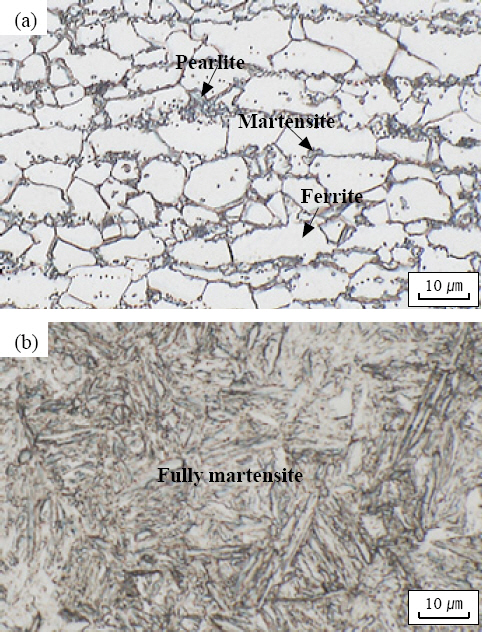
Microstructure for base metals, (a) as-received, (b) hot-stamped

Schematic of hot-stamping heat treatment process (a) heat treatment by temperature, time and (b) results of the surface condition by heat treatment conditions
3. Results and Discussion
3.1 Comparison of weldability according to hot stamping heat treatment conditions
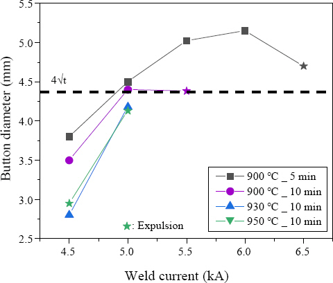
The weldability of Al-Si coated 1.8 GPa grade hot stamping steel sheet according to heat treatment conditions is compared in Fig. 3 and as a result of deriving the available current section according to each condition, there was a difference in the available current section according to each heat treatment condition. This is a result of the difference in button diameter according to the welding current and the current value at which expulsion occurs. In the case of the specimen heat treated at 900°C_5 min, a button-shaped partial interfacial fracture occurred from a welding current of 4 kA. After that, a button diameter of 4√t or more was secured under the condition of 5.5 kA or more, and a narrow available current section of about 1 kA was secured because expulsion occurred at 7 kA. On the other hand, the specimen heat treated at 900°C_10 min did not satisfy the button diameter 4√t due to partial interfacial fracture at 5 kA, and then since expulsion at 5.5 kA occurred, the available current section was not secured. Also, in the case of the specimens under the heat treatment conditions of 930°C_10min and 950°C_10min, interfacial fracture or partial interfacial fracture occurred even under relatively low current conditions, so a perfect button fracture could not be produced. The button diameter of 4√t or more was secured at 6 kA for the 930°C_10 min condition and 5 kA for the 950°C_10 min condition, respectively, but the available current section was not secured due to the expulsion phenomenon. In welding conditions of 5 kA and 5.5 kA, 950 °C_10 min heat treatment condition has a larger button diameter than 900 °C_5 min condition at 6 kA welding condition and 930 °C_10 min condition at 900 °C_5 min condition. It is judged as a result of the difference in the generated resistance heat. Fig. 4 shows the results of comparison and observation of the fractured weld interface through a peel test after welding a specimen manufactured under various heat treatment conditions under the same welding condition of 5.5 kA. All four heat treatment conditions have partial interfacial fractures, but in the case of the 900 °C_5 min condition, partial interfacial fractures including brittle fractures occurred biased to one side. In the specimen under 900 °C_10 min, 930 °C_10 min, 950 °C_10min conditions, partial interfacial fracture including brittle fracture occurred centered on button fracture. The specimen under the condition of 900 °C_10 min had the widest interfacial fracture area, which is thought to be due to the micropores occurring in the center of the weld affecting the fracture. The diameter of the contact surface was the largest at 6.64 mm in the 900 °C_5 min condition. At 900 °C_10 min condition of 6.23 mm, 930 °C_10 min condition of 6.02 mm, and 950 °C_10 min condition of 5.9 mm, the diameter showed a tendency to decrease as the heat treatment conditions increased. This is because the structure and thickness of the alloying layer differed depending on the heat treatment conditions, and the alloying layer affects the contact resistance of the resistance heating of the weld at the initial stage of welding, so the growth behavior of the molten portion is different. In order to observe the effect on the weldability of the alloying layer formed differently depending on the heat treatment conditions, the contact resistance and initial melting behavior were reviewed in Section 3.2. Additionally, Fig. 5 shows the hardness distribution of the weld section under the 5.5 kA welding condition in which a button diameter of 4√t or more was secured under the 900 °C_5 min heat treatment condition in which the available current section was normally secured. Both the base material and the fusion zone (FZ) were composed of martensitic structures, and the overall hardness was distributed as high as about 550 Hv. In the case of the Upper Critical Heat Affected Zone (UCHAZ), which rose to above the Ac3 transformation line, the maximum was about 590 Hv, which was slightly higher than the base material. After the temperature rises to below the Ac1 transformation, it is cooled and some hardness decreased in the Sub Critical Heat Affected Zone (SCHAZ) and the Inter Critical Heat Affected Zone (ICHAZ), where tempered martensite and ferrite fractions increased due to the tempering effect. It was found similar to the hardness results of general welds with increasing hardness at the base material13,14).
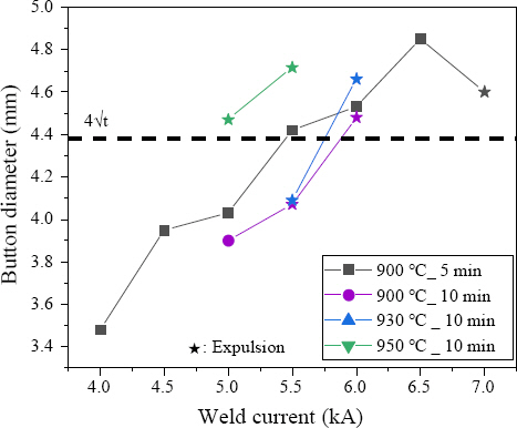
Comparison of weldable current range for various 1.8 GPa-grade hot stamping steels with heat treatment conditions
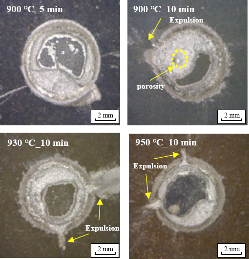
Fracture mode of peel test specimen (weld current : 5.5 kA, weld time : 250 ms)
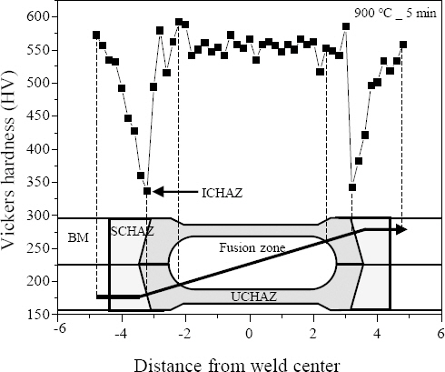
Hardness profiles for 1.8 GPa-grade hot stamping steels with the heat treatment condition at 900°C 5 min (weld current : 5.5 kA, weld time : 250 ms)
3.2 Analysis of alloy layer properties and contact resistance according to heat treatment conditions
The Al-Si coated layer before the hot stamping heat treatment method was applied was about 25-30 μm thick, and the typical chemical composition was about 88% Al, 10% Si, and 2% Fe, and had a melting point of about 600 °C16,17). Fig. 6 shows an optical microscope photograph of the alloying layer under the hot stamping heat treatment conditions of Al-Si coated boron steel. Before the heat treatment, the coating layer was formed with a precipitate of about 4-6 μm thick Fe2SiAl7 intermetallic compound grown into the Al-Si melt coating base18,19). On the other hand, the thickness of the alloying layer increased through the interdiffusion process due to the Kirkendall effect between the Al-Si coated layer and the steel during heat treatment, as Fe diffused from the base material to the coating layer, a diffusion layer in the form of Fe (Al, Si) was formed from the region where the base material and the coating layer contacted. In addition, as the Fe content in the coating layer increased, a complex alloying layer was formed in the form of an intermetallic compound layer forming a band in the form of FeAl2, Fe2Al5, etc.15,19) At this time, as the heat treatment time increased, the Fe component of the base material was sufficiently diffused into the alloying layer, and the diffusion layer was formed thick. The tendency of the intermetallic compound layer in the form of FeAl2 and Fe2Al5 to expand was observed as the heat treatment temperature increased. In particular, under the heat treatment condition of 950 °C_10 min, the intermetallic compound layer was distributed over the entire upper part of the diffusion layer, showing simplified alloying layer behavior compared to the alloying layer under other conditions18,20). for further analysis, As shown in Fig. 7, the alloy layer thickness and contact resistance according to the heat treatment temperature and time characteristics of the hot stamping method were compared. Fig. 7(a) shows the alloying layer thickness characteristics according to the heat treatment conditions compared to the existing Al-Si coated layer. The alloying layer thickness increased by about 5~15 µm on average in proportion to the heat treatment temperature and time. In addition, Fig. 7(b) shows the contact resistance of the alloying layer according to the heat treatment conditions compared to the existing Al-Si coated layer. Compared to the contact resistance of the existing Al-Si coated layer of about 0.028 mΩ, it increased by about 15 times at 900 °C_5 min and 10 min. Under the conditions of 930 °C_10 min and 950 °C_10 min, the values were about 0.70 mΩ and 0.75 mΩ, respectively, which were about 20 times higher. Based on Fig. 6, This is because the thickness of the alloying layer increased as the heat treatment temperature and time increased, and the region of the FeAl2, Fe2Al5 intermetallic compound layer expanded throughout the alloying layer. It is reported that these FeAl2, Fe2Al5- based intermetallic compound layers have high electrical resistance and brittleness, as well as a high melting point of about 1100 to 1300 °C, which is twice as high as the conventional Al-Si coated layer21,22). This causes high heat generation in resistance welding using the resistance characteristics of the contact interface, which is expected to adversely affect weldabilities such as the expulsion of the weld at low current, the reduction in the available current range, and the occurrence of voids and cracks in the weld.
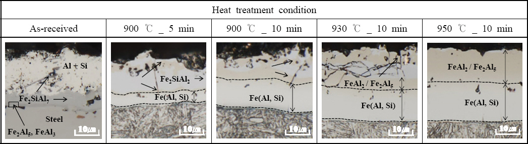
Cross-sectional optical microscope of intermetallic layer with various heat treatment conditions
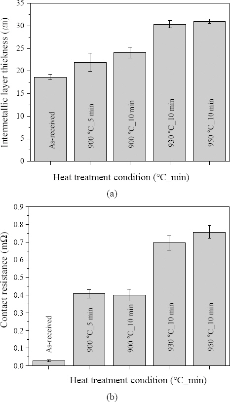
Properties of intermetallic layer with various heat treatment conditions, (a) intermetallic layer thickness, (b) contact resistance
3.3 Analysis of the melting behavior of the alloy layer at the initial stage of welding and the microstructure of the weld
The contact area for energization in the initial welding greatly affects the formation of the corona bond and the stable growth of the molten part, and it is essential to secure a uniform contact area to obtain a sound weld23,24). Fig. 8 is the result of observing the melting behavior of the initial alloying layer in the weld within 50 ms of the welding time, which is a section where the influence of contact resistance due to the influence of the initial alloying layer is dominant. According to each heat treatment condition, the weld interface was compared for 17-50 ms welding time with a welding current of 5 kA. In the case of the 900 °C_5 min specimen in which expulsion did not occur, the alloy layer was uniformly melted in 17 ms, and it was confirmed that the molten portion grew from 50 ms after a sufficient contact area and corona bond were secured in 34 ms. However, In the case of 900 °C_10 min, 930 °C_10 min, 950 °C_10 min specimens, it can be seen that the alloying layer does not melt uniformly at 17 ms and the molten part grows without sufficient contact area and corona bond at 33 ms. In particular, in the case of the 950 °C_10 min specimen, the alloying layer remained in the center of the weld without being pushed out to the outer shell of the weld even at 50 ms when the melt was formed. The difference in the melting behavior of the alloying layer at the initial stage of welding is that as the heat treatment conditions increase, the amount of diffusion of the Fe component in the alloying layer increases, so that the thickness of the alloying layer increases and the melting point rises, causing exothermic phenomena. Therefore, it is judged that the molten coating layer remained in the center of the molten portion because the molten coating layer could not be pushed out to the outer shell because the coating layer was not melted properly at the beginning of welding. Resistance spot welding uses electrodes to locally generate resistance heat in the contacted part inside the plate. Then, A method of forming a joint is by melting a plate and applying pressure. The dynamic resistance curve is a graph obtained by comparing the change in resistance with time and linearizing it with the sum of the initial contact resistance and the bulk resistance during the welding time. Therefore, it is possible to indirectly analyze the phenomena occurring during welding, such as the initial melting behavior, heat generation, and expulsion. In order to compare the effect of the intermetallic compound of the alloying layer changed according to the heat treatment conditions on the weldability, the dynamic resistance curve was measured under the same welding condition of 5.5 kAd as shown in Fig. 9. As the heat treatment temperature and time increased, the initial dynamic resistance value was higher, and expulsion occurred at about 160 ms for the 900 °C_10 min specimen, about 100 ms for the 930 °C_10 min specimen, and about 75 ms for the 950 °C_10 min specimen. This is because as the heat treatment conditions increase, the amount of Fe diffused into the coating layer increases and as the thickness of the alloying layer increases and the Fe-Al-Si compound increases, a sufficient contact area was not secured at the weld interface, and high heat was generated from the beginning of welding, resulting in unstable growth of the melt. Fig. 10 shows the result of observing the weld section after welding under the same conditions at the same welding current of 5.5 kA. In all specimens under all conditions, the nugget had a slanted shape. Due to the high rigidity of 1.8 GPa grade hot stamping steel, melting started in one direction, and the deformation of the indentation was unbalanced. For the 900 °C_5 min specimen, the nugget diameter was about 5.3 mm, so the melting area was sufficiently secured, and no pores were observed. On the other hand, in the case of the 900 °C_10 min, 930 °C_10 min, and 950 °C_10 min specimens, expulsion occurred, so that the melt escaped to the outer shell of the corona bond, and pores at the center of the weld were observed. The size of the nugget diameter decreased because the contact area was not sufficiently secured due to the expulsion phenomenon and the alloying layer. In addition, the alloying layer remained in the form of a film in the corona bond portion of the specimen, and as the heat treatment temperature and time increased, the thickness of the remaining alloying layer in the outer shell portion gradually increased. Additionally. In Fig. 11, the composition of the remaining alloying layer was observed using the EPMA analysis. Although not observed at 900 °C_5 min, an intermetallic layer was observed at the interface between the molten zone and the heat-affected zone under the heat treatment conditions of 900 °C_10 min and 930 °C_10 min. Fig. 11(a) is the result of enlarged observation of the section of the weld where intermetallic compounds were observed, and Fig. 11(b) is the result showing the compositional analysis of intermetallic compounds using EPMA mapping. When it was confirmed that Al and Si components were high and Fe components were low in both 900 °C_10 min and 930 °C_10 min in the intermetallic compound, it was determined that the Al-Si coated layer was an alloying layer in which Fe was diffused during heat treatment. When the Al and Si components appearing in the Fe-Al-Si compound generated from the 900 °C_10 min specimen and the 930 °C_10 min specimen were compared, the Al and Si components showed high strength in the 900 °C_10 min specimen. In the case of the intermetallic compound of the 900 °C_10 min specimen, an alloying layer was formed during the Journal of Welding and Joining process, which escaped to the outer shell of the molten part. The intermetallic compound generated in the 930 °C_10 min specimen was formed differently between the fusion zone and the heat-affected zone because some alloying layer, which did not have sufficient fluidity at the beginning of welding, did not escape to the outer shell of the weld and remained near the nugget. As a result of measuring the hardness of the intermetallic compound using a Micro Vickers hardness tester, the intermetallic compound of the 900 °C_10 min specimen was 375.4 Hv, and the 930 °C_10 min specimen was 379.2 Hv, which was similar to the hardness of the ICHAZ part. Judging from the results of the above-mentioned fracture mode (Fig. 4), since the Fe-Al-Si intermetallic compound has brittle properties, in the case that the Al-Si coated 1.8 GPa class hot plate with relatively high material strength. When fractured, the fracture did not occur in the ICHAZ part and was formed between the corona bond interface and the molten zone and the heat-affected zone and acted as a notch. so, the type of interfacial fracture was different according to each heat treatment condition8,25).

Intermetallic layer melting behavior in the faying surface (weld current 5.5 kA)

Dynamic resistance curve with weld time for various 1.8 GPa-grade hot stamping steels with heat treatment conditions (weld current 5.5 kA)

Cross sections of weld for various 1.8 GPa-grade hot stamping steels with heat treatment conditions(weld current 5.5 kA)
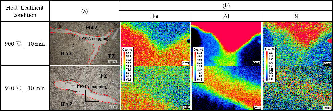
Cross-sections of periphery of welds (a) OM image, (b) EPMA mapping of elemental distribution
3.4 Comparison of Welding Characteristics by Preheating and Current Application
According to previous studies, it has been confirmed that pre-pulse has the effect of minimizing the influence by pushing the coating layer from the center of the weld to the outer shell at the beginning of welding and securing a large contact area at the beginning of welding26-29). Fig. 12 shows the results of comparing the available current section to confirm the effect of prepulse according to the heat treatment conditions based on the welding conditions with pre-pulse applied. The preheating and energization conditions used in the experiment did not cause melting, referring to the results of previous studies. The available current section was compared by selecting the condition of 8 kA and 33 ms as a relatively short welding time and a relatively high current condition where the alloying layer is pushed out of the weld zone to secure a large contact area26). Compared to the single energization condition, the size of the button diameter was increased at the lower limit current of the available current section, and a wide available current section was secured under the condition that the heat treatment condition was not excessive (900 °C_5 min). In the case of the 900 °C_5 min specimen, where the available current section was secured only under the single energization condition, a larger button diameter could be secured compared to the single energization condition. However, among the specimens for which the available current section was not secured under the energization condition, only the 900 °C_10 min condition satisfies 4√t under the 5 kA welding condition, thereby securing a part of the available current section. In the case of the 930 °C_10 min and 950 °C_10 min specimens, it was found that the available current section was not secured as expulsion occurred even under low current conditions. This is because the temperature and time for Fe to diffuse into the Al-Si coated layer are sufficient, and In the case of having a relatively thick alloying layer, a portion of the alloying layer at the interface of the weld could not be pushed out to the outer shell of the weld in the form of a film even when preheating and energizing conditions were used. Because of this, it is judged that the expulsion phenomenon occurred because the growth of the molten part was unstable because a sufficient contact area was not secured.
Comparison of weldable current range using pre heat current welding conditions
4. Conclusion
In this study, the alloying layer according to the heat treatment conditions (temperature and time) of 1.8 GPa grade hot-stamped boron steel plated with Al-Si was compared and analyzed. By comparing the welding characteristics according to the heat treatment conditions, the initial melting of the alloy layer and the melting behavior after welding were analyzed. Also, the welding characteristics applying pre-pulse welding conditions were examined.
1) As a result of comparing the available current section for the heat treatment conditions of the Al-Si coated 1.8 GPa grade hot stamping steel sheet, there was a difference in the available current section according to the heat treatment conditions. This is the result due to the difference in the button diameter according to the welding current and the current value at which the expulsion occurs.
2) the thickness of the alloying layer increased during the hot stamping heat treatment, As Fe diffused from the base material to the coating layer, a diffusion layer in the form of Fe (Al, Si) was formed from the region where the base material and the coating layer contacted. As the heat treatment temperature and time increased, the thickness of the alloying layer increased, and the region of the FeAl2, Fe2Al5 intermetallic compound layer expanded throughout the alloying layer.
3) As the hot stamping heat treatment temperature and time increase, the amount of diffusion of Fe components in the alloying layer increases, increasing the thickness of the alloying layer. The melting point increased, causing an exothermic phenomenon. According to each heat treatment condition, there was a difference in the melting of the coating layer at the initial welding, and there was a difference in weldability due to the melting behavior of the initial coating layer, such as not being able to escape to the outside.
4) The result of comparing the available current section by selecting the welding conditions of 8 kA, 33 ms referring to the results of previous research is that the size of the button diameter increased at the lower limit current of the available current section compared to the single energized condition and wide range of available current was secured under conditions where the heat treatment conditions were not excessive (900 °C_5 min). This is achieved by using preheating and energization conditions when the alloying layer has a relatively big thickness due to sufficient temperature and time for Fe to diffuse into the Al-Si coated layer. Besides, it promotes the melting of the alloying layer at the interface of the weld and easily escapes to the outer shell of the weld in the form of a film.
Acknowledgment
This study has been financially supported by the ministry of Trade Industry(20013403) and Energy and the ministry of Economy and Finance(JA220008) as project.