Dimension Precision and Uniformability Depending on the Interpass Distance Variation of Automated-Wire Arc Additive Manufacturing using 5 Cr-4 Mo Tool Steel Alloy
Article information

Abstract
Die casting molds for aluminum are fabricated using machining billets of tool steels, such as Cr-Mo tool steel. However, this approach has several limitations, including significant material loss and a long lead time. Wire arc additive manufacturing (WAAM) is an alternative fabrication method that yields low material loss and has a short lead time. However, WAAM involves the repetitive stacking of layers based on designed tool paths using CAD/CAM. Thus, the predictability and uniformability of each layer are the most important factors. The interpass distance is an important parameter in a given process; however, studies on the interpass distance of the WAAM process are limited. In this study, it was determined that the interpass distance significantly influences the arc stability owing to the arc interference induced by the variation in distance from the prior deposited pass; more arc interference was observed as the interpass distance decreased. This phenomenon was validated via analysis using a high-speed camera and the variation in the amount of spatter. Furthermore, it was observed that the interpass distance influences the dimensional precision and uniformability. The interpass distance influences the arc interference unless it is greater than 100%. Thus, it is important to determine a point of balance based on the arc stability, dimension predictability, and uniformability of each layer.
1. Introduction
Recently, global automobile companies have encountered a new paradigm due to environmental regulations regarding fuel economy and greenhouse gas emission standards. Most of them are attempting to manufacture lighter vehicles, which directly results in higher energy efficiency. This has led to the replacement of steel by lighter materials such as aluminum die-cast parts and chassis. Aluminum die-cast parts are made by the die casting process and utilize die-casting molds made from kinds of tool steel. The conventional mold fabrication process includes the following steps: i) sourcing the mold base steel for the cavities and other accessories from a massive billet of tool steel, ii) CNC rough machining, iii) heat treatment, iv) fine machining (by milling, drilling, and wire cutting), v) polishing, and vi) the mold assembling1). A large amount of scrap is formed at the rough machining stage because the cavities are machined from large billets of tool steel. This results in material loss, which leads to high material costs. Furthermore, the lead time is too long to finalize the mold-making process. This is because stages iii) to vi) are usually repeated several times till the mold satisfies the required dimension precision.
Die casting molds can be fabricated using metal additive manufacturing (AM) processes as another option. Dozens of these processes have been invented and investigated for decades. They are categorized as powder bed fusion (PBF) and direct energy deposition (DED), and several processes are available in each category1-3). Wire arc additive manufacturing (WAAM) is one of a DED type metal AM processes that deposits a solid metal filler wire using conventional gas metal arc welding (GMAW) as the heat source3,4). The WAAM process can be performed using conventional GMAW equipment and commercial filler materials. Thus, the initial investment is lower compared to other metals AM processes1). Furthermore, it has several advantages, including a high-efficiency energy source5), high deposition rate of 1-10 kg/h6), large lot size7), and high modifiability1). In addition, the WAAM process involves the stacking of weld beads based on the component design obtained using CAD/CAM software. Therefore, material loss and the running time can be reduced by minimizing the number of passes and assigning appropriate tool paths.
WAAM is a stacking process based on the repetitive conventional arc welding to build components. Thus, major process parameters of arc welding are basically significantly affect the performance of the WAAM process; such as the current, the voltage, contact tip to work distance (CTWD), travel speed, torch and travel angles, and shielding gas, etc1,5-7). Meanwhile, in addition to these parameters, there are additional important process parameters; such as the interpass and interlayer distance, since the fabricated components consist of stacked individual beads1,8-10). The interpass distance is the distance between single beads within a layer for multi-track welds, as shown in Fig. 1. The parameter significantly affects the arc stability (mainly due to interference of the arc by the prior pass that is already deposited) and the consequent performance of the process. In AM processes that use a laser as a heat source, the hatch distance, overlap distance, or point distance are similar to the interpass distance in WAAM and are considered to be important factors that control the performance of the entire process. Inappropriate distance parameters can cause variations in the powder density and porosity within the AM component11-13). However, there are few studies on the interpass distance of the WAAM process. Furthermore, the WAAM process is a metal additive manufacturing process, which means it is based on a CAD/CAM design and a robot-based automated process as does 3D printing. Thus, the Automated-WAAM (A-WAAM) process must operate autonomously based on designed schedules. This means that the process parameters in the schedule must ensure consistent performance to achieve high quality and good dimensional precision of the final product considering size, shape, and defect-free for each pass and layer. Predictability and uniformability are the most important factors in the process. Otherwise, A-WAAM does not have a competitive edge compared to other metal additive manufacturing processes. Process monitoring and real-time adaptive control of the process parameters are potential solutions, but they are based on trial and error and are difficult to implement in a practical setting. Therefore, it is important to use process parameters with high predictability and uniformability.
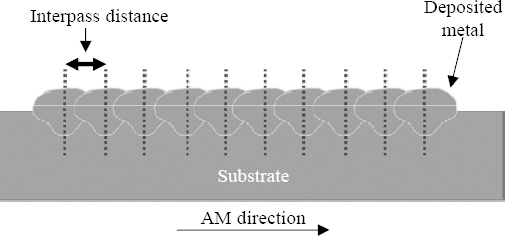
Schematic diagram of interpass distance in an additive manufactured single-layer
Moreover, the heterogeneous surface of single layer due to low uniformability, induced by inappropriate interpass distance, can cause internal defects within the AM component. That is because the A-WAAM component results from the stacking of numerous single layers by scheduled tool paths, and those uneven surfaces due to low uniformability may accumulate and multiply as the stacking of layers has proceeded.
Thus, it is important to understand the impact of the interpass distance of the A-WAAM process, its origin, and how it should be handled for the appropriate design of the schedule. To date, however, most studies have focused on the fabrication of the final components but not on the interpass distance, which can dramatically influence the performance of the A-WAAM process.
In this research, the effect of the interpass distance on the arc behavior of 5 Cr-4 Mo tool steel is discussed. The arc variation induced by changes of the interpass distance was observed and analyzed to find out the origin and effect of this parameter on the arc behavior and the consequent arc stability. Furthermore, the singlelayer A-WAAM components of 5 Cr-4 Mo tool steel with varied interpass distances were analyzed to find out the effect of this parameter on A-WAAM performance especially the dimension precision and the uniformability.
2. Materials and Methods
SCM 440 alloy (low-alloyed steels for machine structural use) plates were used as the substrate with dimensions of 200 (l) × 150 (w) × 30 (t) mm. A commercial 5 Cr-4 Mo tool steel solid filler wire (diameter of 1.2 mm) was used as the deposited metal. The chemical composition of each material is listed in Table 1.

Chemical composition of the materials used in the study
The A-WAAM process was operated based on the cold metal transfer (CMT) welding machine (FRONIUS), a 6-axis robot (KUKA), and a 3-axis sliding fixture for additive manufacturing, as shown in Fig. 2. The process parameters used in this study are listed in Table 2. All parameters except the interpass distance were fixed to determine the effect of the interpass distance on A-WAAM performance1). Each pass was conducted with a length of 150 mm. The single-layer was composed of 10 passes, and the weld was conducted continuously. After one pass ends, the stage moves back to its initial position as well as being offset in AM direction with given interpass distance. And the following passes were welded immediately to obtain enough preheating effect. The peak temperature of A-WAAM components was measured as about 500 °C right after the A-WAAM done.
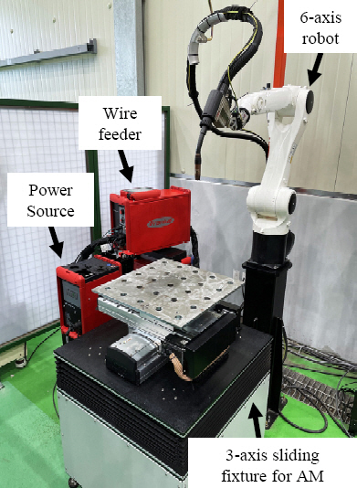
Equipment setup for the A-WAAM process

Input parameters for the experiments
A high-speed camera (PHOTRON) and LED source were used to observe the arc behavior, as shown in Fig. 314). The torch was fixed, and the substrate was moved backward away from the camera using the 3-axis sliding fixture to capture images of the arc. The LED source was set opposite to the camera to observe the wire, prior pass, and substrate during the arcing stage. Images were acquired at 5,000 frames per second.
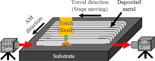
Schematic diagram of the experimental method
The samples were cut using wire cutting and mechanically polished using abrasive silicon carbide paper #1201200 (ALLIED) for cross-section analysis. Chemical etching was conducted using a Nital 2% etchant to analyze the variation in the penetration depth.
3. Results and Discussion
3.1 Interpass distance and consequent arc stability
3.1.1 Designated interpass distance
Based on previous studies, the appropriate interpass distance for the A-WAAM process was determined to be 64% to 74% of the single bead width1,8-10). However, this study aims to determine the effect of interpass distance on the arc behavior and consequent arc stability, i.e., not the optimal interpass distance. Thus, the interpass distances were set as summarized in Table 3. The single bead width for the investigation was 9.75 mm, which is consistent with previous research1). The interpass distances were determined in two ways. The first was based on the conditions for the optimal range according to previous research. This was set from 64% to 72% in intervals of 4%. The other approach was based on the conditions outside the reference range, setting interpass distances that are extremely narrow and wide, i.e., 54% and 82%, respectively.

Designed interpass distances for the test
3.1.2 Arc behavior depending on the varied interpass distance
As mentioned earlier, variation in the interpass distance causes differences in the degree of interference of the prior deposited pass. As such, it changes the shape of the arcing surface and the site of droplet transfer and induces changes in the arc behavior. Consequently, it can be hypothesized that the interpass distance determines arc behavior and stability.
The second and fifth passes in each layer were observed using a high-speed camera to investigate the differences in the degree of interference and the consequent changes of the arc. The acquired images at the moment of maximum arc length are shown in Fig. 4. It was determined that the arc was bent to the prior deposited pass for all conditions. Li et al. reported that the following bead was spread towards the prior deposited pass, and the results were in agreement with this assertion8). It was observed that the arc length and width changed significantly depending on the applied interpass distance. Moreover, variations within the same interpass distance condition were observed when the number of passes was increased.

The arcing images acquired using the high-speed camera at maximum arc length
The schematic diagrams of the arcing images in Fig. 4 were overlapped to present a detailed overview, as illustrated in Fig. 5. It is evident that the interference of the arc owing to the prior deposited pass decreased as the interpass distance increased for the second pass. It should be noted that the surface that the arc struck and the transferred droplet of the melted wire did not exhibit differences in shape because the first pass was a single bead as a bead-on-plate (BOP) type. However, as shown in Fig. 5, the degree of interference showed differences when the interpass distance was changed. Thus, it is reasonable to assume that this phenomenon was induced by the variation in the interpass distance. Furthermore, it was found that the arc length decreased and the width of the arc increased as the interpass distance increased (above 72%), and the degree of interference decreased. In the case of the fifth pass, those tendencies are more pronounced, as shown in Fig. 5. It is notable that the arc interference phenomenon became more severe when the number of passes increased, regardless of the interpass distance. This is mainly due to the accumulation effect of the arc interference as the number of passes increased, which is discussed in section 3.1.3 in detail. However, the degree of change for arc interference was significantly reduced when the interpass distance was increased.

Schematic diagrams of arcing images in Fig. 4 depicting overlapping based on the number of passes. Black dotted lines indicate the center of the solid filler wire. The highlighted outline drawings for interpass distances corresponding to 54, 64, 68, 72, 82% are represented using the colors blue, green, orange, red, and purple, respectively
The arc length is typically an important factor in arc stability in GMAW15). When the arc length is increased, the wobble of the arc increases. Further, Motta et al. reported that the unstable arc deviates the transfer points of droplets and influences the formation of the melting pool16). Thus, it should be noted that it possibly results in an arbitrary droplet transfer position, which decreases the heat (or energy) concentration17). Consequently, the weld bead is irregularly formed, and the possibility of defects increases. Ding et al. also reported that the arc was bent more severe when the narrower interpass distance was given, and height deviation was large in that cases9).
As previously indicated, A-WAAM is a stacking process based on conventional GMAW to fabricate a component in a repetitive manner. Therefore, it also affects the arc stability in the A-WAAM process. It was determined that the prior deposited pass interfered with the following arc from a geometrical viewpoint, and this interference increased the arc length of the following arc. When the interpass distance increased, the interference with the following arc decreased, as shown in Fig. 5. This resulted in a decrease in the arc length with an increase in the width and uniform transfer of droplets. As such, it is possible to obtain a stable arc and to predict and reproduce a uniform layer when the interpass distance increases.
3.1.3 Stability of the arc depending on the variation in the interpass distance
A quantitative analysis was conducted to investigate the effect of the variation in the interpass distance on arc behavior and thus arc stability. Two factors were investigated to evaluate the effectiveness of changes in the interpass distances on arc stability: the angle between the arc center and width (θ) and the ratio of the height at the arc center to the arc width (H/W). Each value was measured using analytic software based on the images shown in Fig. 4, and compared to the BOP (first pass in a single layer) result, as shown in Fig. 6.
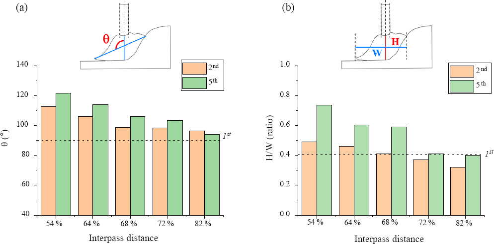
Arc behavior variation depending on the different interpass distances. Effects of (a) angle between the arc center and width (θ), and (b) ratio of the height at the arc center to the arc width (H/W). The black dotted lines in each plot indicate the value of the BOP result (1st pass)
In theory, the arc interference due to the prior deposited pass significantly affects the arc stability, because the prior pass changes the shape of the surface where the arc occurs and the droplet is transferred8,9,15,16). When the arc is influenced by the prior deposited pass, it bends toward that pass, and the angle between the arc center and width (θ) increases. The θ values indicate the degree of interference experienced by the following arc due to the prior deposited pass, as illustrated in Fig. 6a. The θ value of the BOP was 90° and it was assumed to represent a stable arc state because of the absence of interference. The θ value of the 54% condition was the largest among the different interpass distances, and it increased with the increase in the number of passes. This is mainly due to the accumulation effect of the arc interference, as mentioned in Section 3.1.2. The narrower the interpass distance, the more the arc interference, which resulted in a larger θ. The large θ could increase the chance of the droplet transfer position towards the prior bead and is prone to cause uneven bead shape changes. It changes the surface where the arc occurs and the droplet transfers and affects the degree of arc interference of the following pass. Thus, it is reasonable to assume that it accumulates with the number of passes. Moreover, the value of θ gradually decreased with an increase in the interpass distance, as shown in Fig. 6a. When the interpass distance exceeded 68%, it was approximately 100°, and when it increased to 82%, it was approximately 90°. The variation of the θ values revealed that the arc interference decreases with the increase in the interpass distance, which agrees with the hypothesis that the interpass distance determines arc behavior and stability.
Meanwhile, the height of the arc increased when the arc interfered with the prior deposited pass and was bent. An increase in the arc height indicates an increase in the arc length, came up with increase in θ, and it which results in a decrease in the arc width. This causes the degradation of the arc stability, as discussed previously. Thus, the ratio of the height at the arc center to the arc width (H/W) also indicates the degree of arc stability. The results for the H/W values are shown in Fig. 6b, Fig. 6and a schematic diagram of the measuring criteria is provided above it. The H/W value of the BOP was approximately 0.406, which was assumed to correspond to a stable arc. During the second pass, the H/W value was higher than that of the stable arc when the interpass distance was lower than 68%. However, it was slightly lower than that of a stable arc when it was higher than 68%. Thus, the interpass distance had little effect on the arc interference and the consequent arc stability at that time. However, it was found that the H/W values increased steeply when the interpass distance was lower than 68% for the fifth pass. Further, it was observed that the H/W value was doubled compared to that of the BOP when the interpass distance was 54% during the fifth pass. In other words, the arc length was too long to obtain a stable arc. This is mainly due to the extremely narrow interpass distance, causing severe arc interference, as discussed with Figs. 4, 5, and 6a. The conditions for which the interpass distance was higher than 72% had H/W values similar to those of the stable arc state, despite there was also an increase in the H/W values owing to the increase in number of passes. Similar to the case of θ, it was determined that the arc interference decreases with an increase in the interpass distance, which is in agreement with the hypothesis.
The θ and H/W values are the factors that directly account for the arc stability. It was observed that the values changed dramatically when the interpass distance was changed. The change in interpass distance caused a variation in the arc interference, as discussed in the previous section. This implies that the arc interference varied with the change in the interpass distance and greatly affected the arc stability in the A-WAAM process. Furthermore, it is reasonable to consider that there is a critical interpass distance to achieve stable arc behavior in A-WAAM process, given that the values of θ and H/W maintain balance with those of the stable arc state (values of BOP in this study) above a threshold interpass distance. D. Ding et al. reported on the existence of a critical d/w (the interpass distance in this study) and stated that stable overlapping was observed above the critical d/w9). This is in agreement with the results and hypothesis presented in this study.
3.2 Effect of the interpass distance and consequent arc stability variation on the A-WAAM process
3.2.1 Designated interpass distance
The effect of the change in the interpass distance on the arc behavior and stability was observed and discussed in Section 3.1. However, the extent to which it affects the quality and uniformability of the A-WAAM process is unclear. Therefore, experiments were conducted using the optimal range of the interpass distance based on previously reported results1,8-10). The interpass distances were set as listed in Table 4 with a range of 64%-72% at intervals of 2%.

3.2.2 Arc stability and the amount of spatter
The single layers of the A-WAAM process were well deposited for five interpass distances, as shown in Figs. 7a-e. It is evident that the amount of spatter is different for each sample. In GMAW, it is common for spatter to be formed when the arc is unstable, the surface condition is not clean, or the welding parameters are not appropriate18). However, the surface conditions and welding parameters are given equal here. Thus, it is reasonable to assume that the arc stability changed because the interpass distance was varied, as discussed in Section 3.1. The size of the substrates was equal; thus, the amount of spatter attached to the surface of the substrate, as depicted by the red arrows, was inspected visually, and the result is shown in Fig. 7f. It is notable that the amount of spatter decreased significantly when the interpass distance was greater than 68%. Moreover, when it increased to 72%, there was minor spatter, as shown in Fig. 7e. This phenomenon also indicates that the arc interference varies with the change in the interpass distance and significantly affects arc stability in the A-WAAM process.
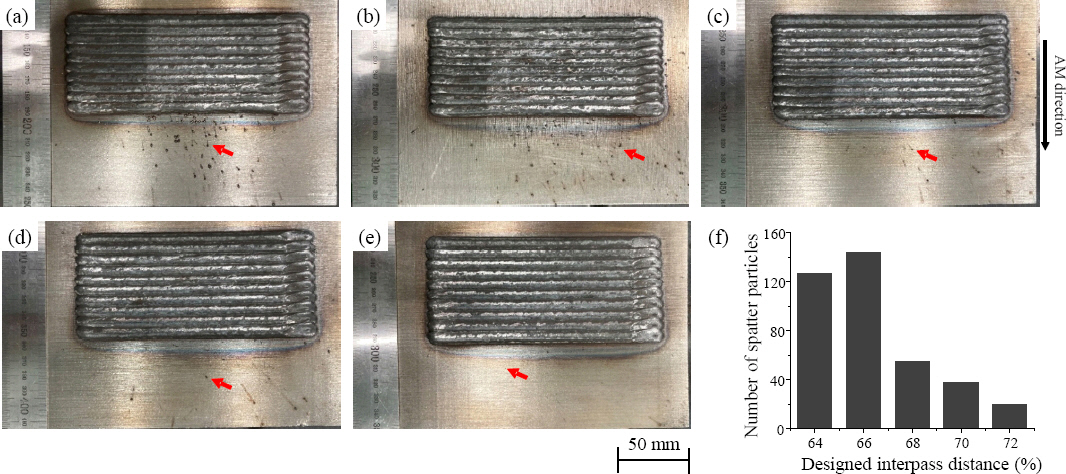
Top view images of each sample for designed interpass distances of (a) 64%, (b) 66%, (c) 68%, (d) 70%, and (e) 72%. The number of spatter particles on the surface of the substrate was counted and plotted in (f)
3.2.3 Cross-section analysis
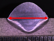
The samples were cut, mechanically polished, and chemically etched to observe their cross-sections. Internal defects were not found in the sample, and the layers were well deposited, as shown in Fig. 8. It was found that the width of the single layer increased as the interpass distance increased. It should be noted that if the performances of the deposited metals (e.g., dimension precision, defect, spatter, etc.) are similar, then a wider width of the single layer is advantageous in the AWAAM. This is because it can reduce the total number of tool paths and hence reduce processing time and cost.

Cross-sections for dimension precision analysis corresponding to designed interpass distances of (a) 64%, (b) 66%, (c) 68%, (d) 70%, and (e) 72%
3.2.4 Dimension precision in horizontal direction
The dimension precision of a single layer in the horizontal direction of each sample was theoretically analyzed. The single layer was composed of ten passes of a single bead (n), and the width of the single bead (WB) was 9.75 mm, as mentioned as a footnote in Tables 3 and 4. The designed width of the single layer (DLW) on the interpass distance (DI) was calculated using the following equation, using the parameters defined in Fig. 9.
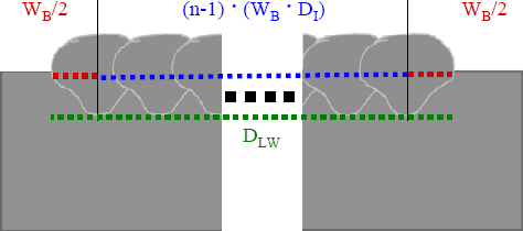
Schematic diagram of the method used to obtain the designed single layer width
where,
DLW : designed single layer width
WB : single bead width
n : number of passes
DI : designed interpass distance
The actual width of the deposited single layer was measured (MLW) using analytic software based on the images in Fig. 8. Then, the accuracy of the dimension in the horizontal direction (A) was obtained using the following equation:
where,
A : accuracy of the dimension
MLW : measured single layer width
The calculations and results of the analysis are presented in Table 5. It was determined that the dimension precision was accurate for all conditions, except for the 64% interpass distance (approximately 98% accuracy) in the horizontal direction. Hence, it can be concluded that the interpass distance had little impact on the dimension precision in the horizontal direction of the A-WAAM process in the range of 64% to 74%.

Dimension precision analysis result of a single layer width
It was observed that the width of the layer increased when the interpass distance was increased. This is expected because the moving distance in the horizontal direction increased due to an increase in the interpass distance between each pass. Nevertheless, it is advantageous considering the reduced processing time of the A-WAAM. The aim of this process is to obtain a final product with a specific size based on a design. The number of tool paths in the A-WAAM process is determined by calculating the size of the final product divided by the size of the bead or the layer. Therefore, the total processing time and the number of tool paths required to fabricate a component with a specific size can be reduced, assuming that the width of a single layer is wider and the number of tool paths is the same.
3.2.5 Uniformability evaluation in the vertical direction
The uniformability evaluation of the single layer in the vertical direction of each sample was inspected. Four factors were used to evaluate the effectiveness of the interpass distance on the uniformability evaluation in the vertical direction, as shown in Fig. 10: the height of the bead top surface (HT), the depth of the penetration (DP). Subsequently, each value was standardized for the objective evaluation using the following equations:
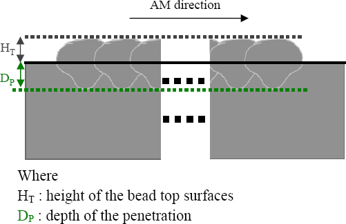
Schematic diagram of the measuring method used to obtain the height and depth values
where,
m : mean
n : number of values
υ : variance
σ : standard deviation
xnew : standardized value
The deviation of HT values indicates the uniformity of the surface where the following layer deposited. It has a high possibility to form differences in height within the layer, and has a high chance to form an inclined component shape on one side with side collapse or any other defects when it additive manufactured further8,9,19-21). The A-WAAM process is based on the concept that the fabricated component is the result of the stacking of dozens of layers. In other words, the uneven layer surface would be a highly potential defect former, and this phenomenon would be accumulated as the process progressed hence intensified. Defects such as unfulfilled areas, cracks, delamination, and collapse can occur if the uniformability of each layer is low, and its dimension is unpredictable1,21-25). Therefore, it is important to use the interpass distance which is possible to ensure the uniform surface of each layer.
The HT values are plotted in Figs. 11a-11e. HT values for an interpass distance of 66% or below are severely scattered, and hence, wide 95% confidence bands are observed in Figs. 11a and 11b. The wide deviation of the bead top surface height is mainly due to the unstable arc induced by the arc interference, as discussed in Section 3.1. However, the HT values for interpass distances of 68% or above exhibit a linear relationship with a small slope, as illustrated in Figs. 11c-11e. As a result, the 95% confidence bands also show a very narrow range. This implies that an interpass distance of 68% or above could ensure the uniformability and predictability of the bead surface height, which is advantageous for the A-WAAM.
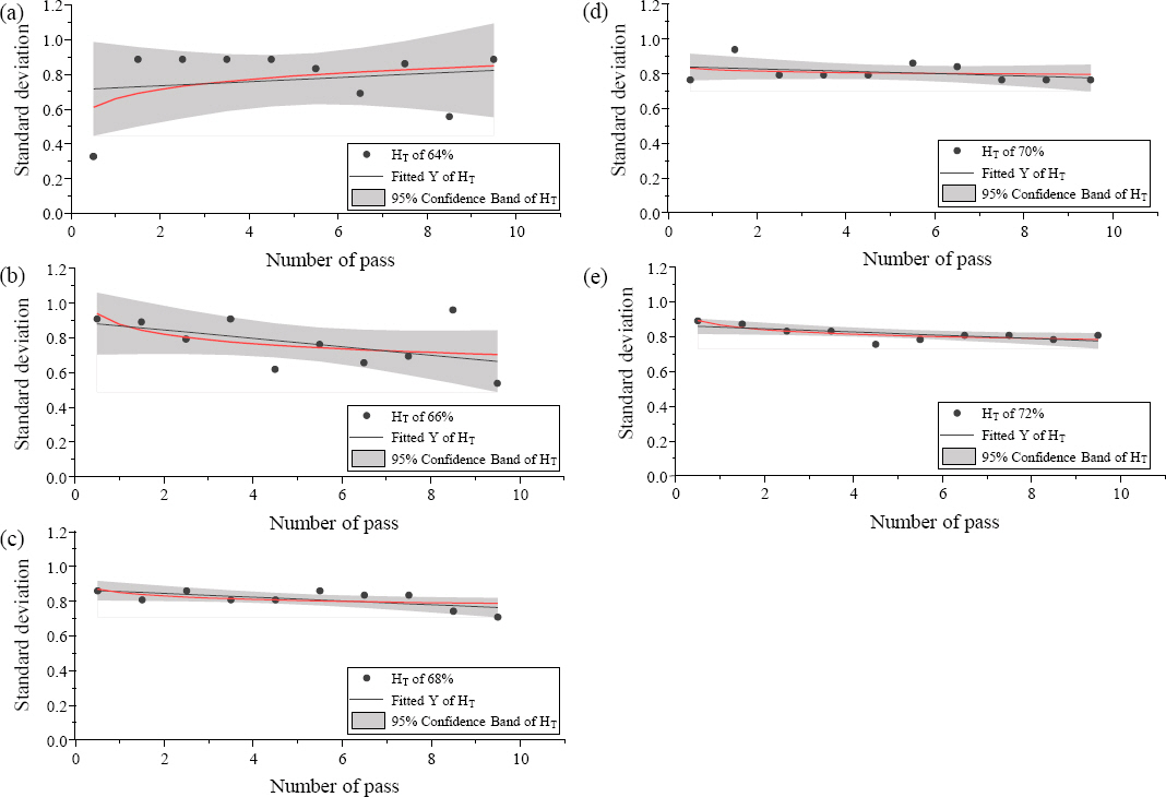
(a) to (e) Standardized HT values of each sample. The black dots represent the xnew values and the black lines indicate the corresponding trend lines. The bold red lines represent the trend line of the fitted Y, and the gray areas correspond to the respective 95% confidence band
The deviation of DP values indicates the uniformity of the heat concentration position and remelting amount of prior layer during the A-WAAM of the following layer. The DP values are plotted in Figs. 12a-12e. DP values for interpass distances of 66% or below were severely scattered; hence, a wide range of the 95% confidence bands is observed, as shown in Figs. 12a and 12b. The high fluctuation of the penetration depth of the deposited metal is mainly due to the unstable arc induced by arc interference and the consequent arc bending towards the prior deposited pass. The unstable arc results in the wobble of the arc, thereby inducing arbitrary droplet transfer and a decrease in the heat (or energy) concentration, as discussed in Section 3.1.2. Consequently, this resulted in a high fluctuation of the penetration depth of the deposited metal within a single layer. This directly leads to the degradation of the uniformability and predictability of the dimension and the quality of a single layer, hence not suitable for the A-WAAM process. Furthermore, it was determined that the dispersion behavior of the DP values for interpass distances of 66% or less was similar to that of the HT values. This also implies the occurrence of wobble of the arc, thereby inducing arbitrary droplet transfer and a decrease in heat (or energy) concentration. Given that the input process parameters are the same, the amount of melted metal is also the same. In this case, the height of each bead increases when the depth of penetration is shallow and vice versa. As discussed for the HT values, the A-WAAM process involves the stacking of dozens of layers. Thus, there is a high likelihood of the occurrence of defects, e.g., the inclination of the top surface to one side and/or the formation of defects such as side collapse1,21-23). When the DP values of the interpass distances were 68% and 70%, comparatively uniform dispersion of the trend line and narrow 95% confidence bands were observed, as shown in Figs. 12c and 12d. However, the values were still scattered at some points, and the trend lines had a slight slope. In contrast, the DP values at an interpass distance of 72% exhibited a very uniform trend line; hence, the 95% confidence band was extremely narrow, as shown in Fig. 12e. Uniform remelting of the prior layer can occur, and high uniformability and predictability are expected for an AWAAM process.
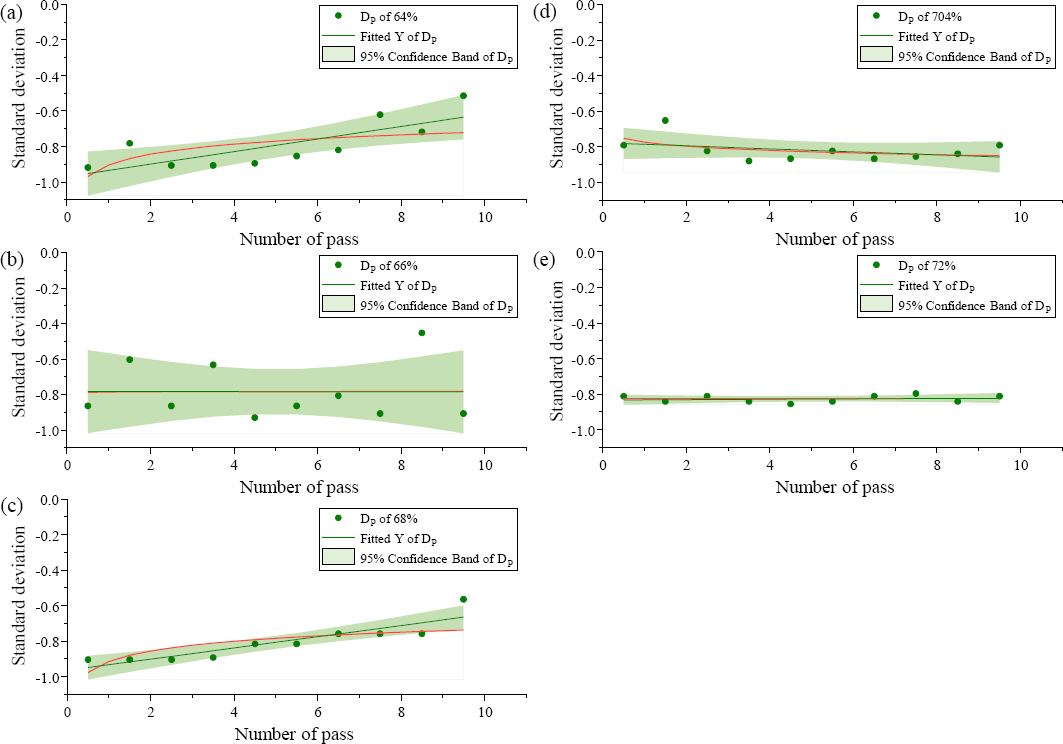
(a) to (e) Standardized DP values of each sample. The green dots represent the xnew values, and the green lines indicate the corresponding trend lines. The bold red lines represent the trend line of the fitted Y, and the gray areas correspond to the respective 95% confidence band
Two particular geometrical factors were evaluated to determine the effect of the interpass distance on the uniformability in the vertical direction, and each factor corresponded to a similar critical interpass distance to ensure predictability and uniformability. Li et al.8) and Ding et al.9) also found the critical interpass distance of the copper coated steel wire and reported that as about 74% to ensure the stable overlapping. In this study, the HT and DP values showed that an interpass distance of 68% could be a critical value.
4. Conclusions
In this study, it was investigated the effect of interpass distance variations on the arc stability, and its effectiveness on the A-WAAM process of 5 Cr-4 Mo tool steel. The main conclusions are as follows:
1)The lower the interpass distance, the greater the occurrence of arc interference.
2)Investigations of the θ and H/W ratio revealed that the arc interference and arc stability change. The arc stability was degraded as the interpass distance decreased, resulting in high θ and H/W ratios.
3)The amount of spatter varied as the interpass distance was changed. The greater the interpass distance, the lesser the amount of observed spatter. This is mainly due to changes in the arc stability associated with the variation in the interpass distance.
4)The dimension precision in the horizontal direction matched the designed width of the single layer under all conditions. It was also observed that the width of the layer increased as the interpass distance increased. This occurred because the moving distance increased with the increase in the interpass distance. Nevertheless, this is advantageous from the viewpoint of the processing time, which can reduce the total number of tool paths needed to obtain a specific component size.
5)The uniformability of the single layer in the vertical direction was investigated using two geometrical factors which HT and DP. It was determined that the critical interpass distance required to ensure predictability and uniformability of the single layer. The interpass distance of 68% or more resulted in uniform dimension precision in the vertical direction and could be utilized in an A-WAAM process.
6)The effect of the interpass distance on the AWAAM process was determined, and the critical interpass distance for 5 Cr-4 Mo tool steel was obtained. The A-WAAM component results from the stacking of multiple single layers by scheduled tool paths. The presence of the heterogeneous surface of every single layer should be avoided, because it is given as a surface where the following layer would be additive manufactured and has a high chance to form an internal defect due to uneven surface. Thus, the critical interpass distance of the A-WAAM process has to be considered carefully before stacking multiple layers on that.
7)The arc interference is detrimental to the uniformability of single layers, but it cannot be completely eliminated unless the interpass distance was greater than 100%. And the arc interference is mainly caused by the morphological and geometrical interference from a combination of the given interpass distance and the shape of prior deposited pass. Thus, it should be investigated a point of compromise based on the arc stability and dimension predictability or uniformability in the early stage of the A-WAAM process design stage, regardless of what the material used.
The effect of the interpass distance on the A-WAAM process is evident. Moreover, the interlayer distance is another process parameter for which the distance in the z-direction between successive layers should be carefully considered in an A-WAAM process. The variation in the interlayer distance could result in variations in the CTWD. Thus, it probably also has a significant impact on the arc stability and the performance of the process. Therefore, research on the effect of interlayer distance in A-WAAM processes should be also conducted to improve their performance.
Acknowledgement
This research was conducted with the support of the Ministry of Economy and Finance (MOEF) for a study on “Development of Smart Manufacturing Technology for Low Temperature Fuel Tank for LNG Ships (JA- 210008).”