Weldability of Aluminum Alloy and Hot Dip Galvanized Steel by AC Pulse MIG Brazing
Article information

Abstract
This study investigates the weldability of dissimilar materials, such as Al6061-T6 aluminum alloy and hot dip galvanized (GI) steel, via AC pulse metal inert gas (MIG) brazing. Notably, the brazing mechanism was investigated for different electrode negative (EN) ratios. The results showed that as the amount of deposition increased with the EN ratio, throat thickness, wetting length, and leg length also tended to increase. Furthermore, it was confirmed that as the EN ratio increased, a thin intermetallic compound (IMC) layer was deposited due to the suppression of IMC growth caused by the low heat input at the joint interface.
1. Introduction
In the face of grave crises such as global warming and resource depletion, CAFE (Corporate Average Fuel Economy) standards are being enforced upon the automotive industry worldwide. In fact, among all global industrial sectors, GHG (Green House Gases) emissions from transportation alone amount up to 25%1).
For this, the use of non-ferrous metals such aluminum alloy or magnesium alloy as material for automotive body has gradually multiplied over the years. Therefore, it is imperative to acquire the technology for the joining of dissimilar materials between steel and non-ferrous metal2,3).
The dissimilar materials used in the weight reduction of the automotive body are mainly aluminum alloy and steel. As in the case of dissimilar material joints, it is extremely difficult to secure appropriate strength and durability due to the intermetallic compounds layer that form at the bonding interface during fusion welding4).
In particular, research on using aluminum alloy as lightweight material is actively conducted. Aluminum alloy has a specific gravity of only one third of that of steel, and are advantageous in both formability and corrosion resistance5). The application of hot-dip galvanized steel with improved corrosion resistance, to the making of the automotive body is growing as well6).
To discover the most effective way to join steel and aluminum alloy, many researchers have studied various methods including explosion welding, ultrasonic welding, friction stir welding, laser welding, laser-hybrid welding, and arc brazing7). However, application of these methods is problematic in that low productivity and expensive equipment8).
Recently the arc brazing process has been adopted as the technology of joining aluminum alloys and stainless steel. AC pulse MIG brazing is arc welding, based on alternating between direct current electrode positive (DCEP) and direct current electrode negative (DCEN) repeating pulsed waveforms, and it reduce spatter and high quality of weldability. Therefore, this method that can significantly improve the quality of the joints with periodic transfer9-13). Furthermore, the amount of heat input in base material is less because it uses pulsed current instead of direct current (DC). Subsequently, using AC pulse can be obtained with large bonding area in spite of less heat input.
This study has tried to apply AC pulse MIG brazing to join dissimilar materials Al6061-T6 aluminum alloy and GI steel. In particular, the effect of EN ratio on the brazing mechanism and weldability in joints has been investigated and evaluated.
2. Experimental Procedure
In the present study, 2 mm thick Al6061-T6 aluminum alloy sheets and 2mm thick GI steel sheets, whose dimensions were 200 mm (L) × 100 mm (B) were welded by AC pulse MIG brazing. As shown in Fig. 1, with an overlap joint of 20 mm, the lap joint of 2 mm thick dissimilar materials was conducted without any gaps in between. 4047 aluminum alloy wire with a diameter of 1.2mm was used as filler material, and the CTWD (Contact tip to work distance) was fixed at 15 mm. In addition, the shielding gas used was 100% Ar gas with a flow rate of 18 l /min. In order to investigate the effect of EN ratio on weldability of joints, the EN ratio was varied at 0%, 10%, and 20% for welding current of 50 A, 60 A, and 70 A.
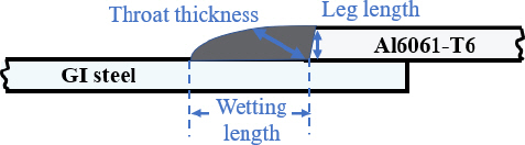
Schematic of Al6061-T6 aluminum alloy and GI steel lap joints
The welding process parameters are shown in Table 1. The chemical compositions and mechanical properties of Al6061-T6 aluminum alloy, GI steel and 4047 aluminum alloy filler wire used in the experiment are shown in Table 2, 3, and 4, respectively.

Welding parameters


The throat thickness, leg length, and wetting length of joints with EN ratio [Unit: mm]
The AC pulse MIG welding machine and 6-axis robot used in this study are the DW-300 and FD-V6, manufactured by Japanese company OTC Daihen as shown in Fig. 2.
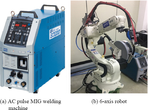
AC pulse MIG welding machine and 6-axis welding robot
3. Results and Discussions
3.1 Bead profiles
Fig. 3 shows the bead formation with the EN ratio for the joining of Al6061-T6 aluminum alloy and GI steel. All experiments were conducted under the conditions at EN ratio of 0%, 10%, and 20% for welding currents of 50 A, 60 A, and 70 A.

Bead profiles with EN ratio
The throat thickness, leg length, and wetting length of joints are shown in Table 4.
As shown in Fig. 3, with increases in the EN ratio, the melting rate and deposition rate of filler material increase, and less Zn damage to the joint reduces the occurrence of porosity in the root area and inside of joints19,20). It was observed that as the EN ratio increased, throat thickness, leg length, and wetting length tended to increase slightly regardless of different currents. In order to achieve good weld strength, an effective leg length with more than 2 mm of objective sheet thickness must be generated. At the welding current of 50A and 60A, the actual leg length over 2mm could be obtained. It was also possible to obtain a longer wetting length and throat thickness under 60A than 50A. This means that welding current of 60 A produces more sound joints, compared with that of 50A and 70A.
3.2 Tensile-shear load
The results of the tensile-shear load tests are shown in Fig. 4 and Table 5. As the EN ratio increased, the tensile-shear load increased regardless of welding currents. This is attributed to longer throat thickness, leg length, wetting length and thinner intermetallic compounds layer formation, caused by high deposition rate and low heat input to the base metal.
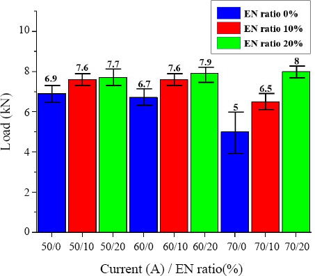
Tensile-shear load with EN ratio for various welding currents

Results of tensile-shear load test
The maximum tensile-shear load was acquired at 8.0 kN when the welding current was 70A and EN ratio was 20%. However, in the cross-sectional analysis, porosity occurred at the root area even under the same conditions, which can cause of fatal defects in the stress concentration area. Under the condition of a welding current of 60A and EN ratio of 20%, porosity was not found at the root area, and the maximum tensile-shear load was acquired at 7.9kN.
As a result, with an increase in the EN ratio, the tensile-shear load also gradually increased at all welding currents 50A, 60A, 70A, and the highest tensile-shear load was found at 20% EN ratio.
In all tensile-shear load tests, local plastic deformation occurred intensively at the root and the toes are, as shown in Fig. 5. The fracture occurred in heat affected zone of Al6061-T6 aluminum alloy side, which heat affected zone of heat treated aluminum alloy is weakest area due to precipitation process.
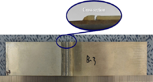
Fractured specimen of tensile-shear load test
3.3 SEM-EDS analysis
At the welding current of 50A and 70A, an effective leg length with more than 2 mm, longer wetting length and throat thickness could not be obtained, compared with those of 60A. Thus, this study intended to investigate the effect of EN ratio on intermetallic compound layer formation in joints at the welding current of 60A.
SEM analysis was carried out to examine the weldability of Al6061-T6 aluminum alloy and GI steel by AC pulse MIG brazing under the conditions of 0%, 10%, 20% EN ratio in 60 welding current.
Fig. 6 shows the SEM images of joint interface at EN ratio of 0%, 10%, 20% in welding current of 60 A. Under the condition of EN ratio of 0%, the average thickness of the IMCs was 4.96㎛. Under EN ratio of 10%, the thickness was 4.69㎛, and for EN ratio of 20%, 2.41㎛, respectively. From the results, it can be confirmed that the growth of the IMCs was suppressed as the EN ratio increased. This is because although the melting amount of the filler material increases as the EN ratio increases, the lower heat input leads to the decrease in the IMC layer formation at the joint interface between the filler material and GI steel.
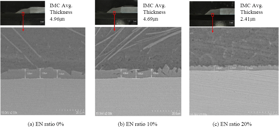
SEM images of joint interface at EN ratio of 0%, 10%, 20%(2000 magnification ratio)
For an analysis of the composition of the IMC formed at the EN ratio of 20% in welding current of 60A, EDS analysis was performed. Fig. 7 shows the results of the EDS analysis on intermetallic compounds layer. The EDS analysis shows the constituent of Al, Fe, Zn, and Si. In addition, the amount of Fe in the area presumed to be IMCs gradually decreased from the GI steel interface toward the aluminum material. In contrast, aluminum gradually increased. Zn, the plating layer of GI steel, has a melting point of about 420℃ and a boiling point of about 907℃, and thus evaporated due to the temperature gradient of the arc during brazing. As a result, the content distribution in the entire section was low, and it is understood that the content distribution slightly increased as it went from the center of the arc with the highest temperature toward the GI steel material.
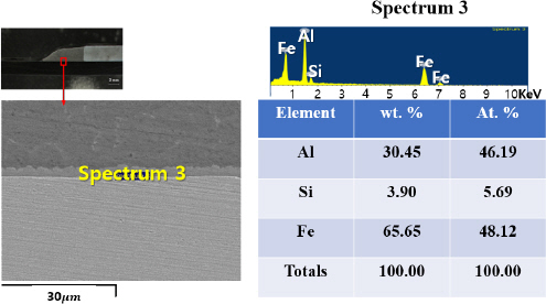
EDS analysis on intermetallic compounds layer
In the case of Si, 4047 aluminum alloy wire was welded to the aluminum base material and the GI steel base material when the filler material was melted. It is presumed that some Si diffused into the joint interface layer to form an Al-Fe-Si ternary phase. The sight of Al being mixed with Fe can be seen, and from this, the formation of the IMC layer can be concluded.
For EDS analysis, a spot assumed to be the IMC layer was designated. According to the result of the analysis, Fe, Al, and Si were detected. It is believed that the during the initial brazing, growth of the Fe-Al based IMC was inhibited because of the melting and vaporization of Zn, the plating layer of the GI steel interface, and the diffusion of Si constituent of the filler material into the Gl steel interface.
4. Conclusion
In this study, weldability according to EN ratio were evaluated in the AC pulse MIG brazing of Al6061-T6 and GI steel. For this, the mechanical properties and brazing mechanism according to the EN ratio were investigated.
1) When EN ratio was 20%, high tensile-shear loads were obtained under all conditions of welding currents, 50A, 60A, and 70A. With the increase of EN ratio, the melting rate and deposition rate of filler material also rose, along with the tendency of throat thickness, wetting length, and leg length to increase. An effective leg length with more than 2 mm, longer wetting length and throat thickness can be achieved under the welding current of 60A, and generation of porosity reduces in the root area and inside of joints in EN ratio of 20%.
2) From the SEM analysis, it could be confirmed that as the EN ratio increased, thinner intermetallic compound layer was achieved due to the suppression of growth of the intermetallic compounds layer caused by lower heat input to the joint interface.
3) According to the EDS analysis, Fe-Al-Si was detected in the intermetallic compound generated at the bonding interface between Al6061-T6 and GI steel. It can be deduced that the ternary Fe-Al-Si mixed layer was formed due to the following factors: the melting and vaporization of Zn, the plating layer of GI steel, during the first brazing and the diffusion of the Si constituent of the filler material onto the joint interface.
4) Thus, in terms of mechanical and microstructural characteristics, it could be concluded that the optimum welding condition was a welding current of 60A with EN ratio of 20%, showing the maximum tensile-shear load of 7.9kN and thinnest thickness of intermetallic compounds layer of 2.41㎛.