Epoxy Polymer Solder Pastes for Micro-Electronic Packaging Applications
Article information

Abstract
Epoxy solder pastes are widely used in microelectronic packaging for joining die, interconnects, screen displays and as a heat dissipaters. Due to their simplicity and high reliability in chip or package bonding, epoxy solder pastes have been recently paid great attention as a competitive bonding material. The epoxy-based pastes are composed of conducting fillers (solder powder, metallic particles) mixed with epoxy polymer. The bonded joint is robust and has a higher strength after the curing of the epoxy polymer during joining. The inclusion of epoxy as a matrix also alleviate the problem of short-circuiting caused by metallic whisker formation. In view of these advantages, epoxy solder is highly attractive amongst electronic packages and in automotive cars. In this review, we have summarized the background and recent developments in the field of epoxy- based solder pastes for electronic and automotive interconnection. Further improvements to improve this technology is also discussed in detail.
1. Introduction
In the last few decades, the use of various polymers as a prime component for the development of solders and packaging such as solder pastes, and no-clean solders have earned great attention in the electronic market1-4). Several notable application of these epoxy solders includes bonding of substrates, liquid crystal display (LCD) screen and surface-mounted devices on printed circuit boards (PCBs). As a consequence of these developments, epoxy based bonding materials can be used as a substitute for the solder material, sealants, interconnecting and shielding material as well as low-temperature brazing5-12). Compared to the counter bonding materials (solders and brazes), epoxy based solders take part in two important functions: (1) formation of robust joints between the two counter substrates and (2) maintain the electrical continuity among the bonded surfaces. In the case of electrically conductive adhesive (ECA), polymer matrix (epoxy, silicone, polyamide or polyurethane) is used for dispersing conducting particles13-14). Various types of conductive fillers can be used, for example, carbon, graphite, and micro- or nano-particles (Silver, Copper, Aluminium, Nickel, etc). When no- clean solder is used, the solder powder is the filler in the epoxy, also known as epoxy solder paste. This provides a stable electrical conductivity due to the formation of an insulating layer over the joint and prevents short-circuiting. The filler materials improve the mechanical properties, thermal conductivity, and therefore, can also be used to tailor the composite thermal expansion, conductivity, and thermal resistance15,16).
In this paper, we overview epoxy polymer based solder pastes which are expected to be widely used in the future. We first introduce the technical principle and application field of the material, comparison to traditional Sn-Pb solder and future guidelines and improvements in this technology will be summarized.
2. Historical perspectives of lead-free soldering
We first discuss the background of this joining technology including the conventional soldering and brazing materials. There are various types of bonding materials such as solders, brazes, welding rods, mechanical fasteners, etc. We cannot join two metals using adhesive or glue, and therefore, we need metallic fillers, brazes and different bonding materials depending upon the application requirement. We will deal with mostly on epoxy type solders with a focus on solder/brazes joints in this review.
2.1 Lead-free soldering
In view of the various concerns raised by the electronic research community, such as according to European Directives, use of lead-bearing solders is restricted in consumer electronics due to the environmental and health hazard nature of Pb17-22). In view of these concerns, lead-free regulations have been passed worldwide in the last few decades. Various types of solders showing similar characteristics to Sn-based solders are available in the market. Table 1 shows the most commonly used lead-free solders such as Sn-3Ag-0.5Cu, Sn-3.5Ag, Sn-0.7Cu, Sn-9Zn, Sn-58Bi, etc. Though most of these solders are promising, however, none of them have been found to replace completely Sn-Pb. This is due to the formation of several IMCs or brittle phases inside these solder matrices.

Some important developments in lead-free solders in modern microelectronics
Further improvements are done to avoid these IMCs and brittle secondary phases and nanocomposite solders were developed with a few success reported in the literature18). Several types of metallic or non-metallic nanoparticles, as well as carbon nanomaterials, were used to refine the IMCs and control microstructure in the last decades28-31). A similar strategy is also adopted to improve the various brazing fillers to join the aluminum components in the industries with some promising results9,10). However, the problem of segregation of high energy surface active nanoparticles and their dispersion in the metallic matrices is inevitable.
3. Epoxy based bonding materials
A very attractive development has been made in the field of epoxy-based solder pastes. In these materials, the matrix is a polymer as compared to traditional metal matrix composite solders. Compared to conventional tin/lead (Sn/Pb) solders, ECA offers various advantages, for example, thermomechanical stresses are relieved to some extent due to the higher flexibility, heat sensitive materials can be used easily due to a lower curing temperature; high resolution for fine-pitch interconnections can be achieved with simple fabrication methods, economically and environmental friendly32-34). According to the latest market study released by Technavio, the global electronic adhesives market is expected to rise at 10% of the compound annual growth rate during 2017-202035). The report classifies the global electronic adhesive market into four sectors, e.g., electrically and thermally conductive adhesives, UV curing, and other adhesives. Due to the increased usage of electronic gadgets, high-end smartphones, emerging IoT combined with the reduced prices of electronic components and high-density interconnections are the main driving forces for triggering this growth. The rapid development in automotive electronics is an important factor in this growth. The auto manufacturers are now refining and adding enhanced safety and comfort features to the car and automobiles to gain an edge in this competitive market space which will create new demand for new solder pastes, and thus driving the market forward.
3.1 Characteristics of solder pastes and epoxy based bonding
In recent years, epoxy based bonding materials are formulated by mixing conducting powder particles (or solder powder) with the epoxy resin. Unlike conventional solder pastes, epoxy solder does not require the surface to be cleaned after joining. The role of the fluxing agent is replaced by the epoxy36). The raw materials used for the epoxy formulation are hardeners, accelerators, thixotropic agents and other additives in a proper ratio. The various characteristics of epoxy-based formulations over the conventional approach are given in Table 2.

3.2 Advantages of epoxy-based bonding materials
Epoxy based soldering materials have several advantages compared to traditional Sn-Pb solders18,36). The various advantages offered by epoxy-based bonding materials are summarized as:
1) First of all, it is lead-free approach and is consistent with the restriction of hazardous substance (ROHS) and waste electrical and electronic equipment (WEEE) directives.
2) The curing temperature of epoxy is much lower than the reflow temperatures of solders (80-150°C). This is important to delay the temperature of epoxy below the sealing point of the solder.
3) Joining and curing at high temperature occurs simul- taneously.
4) High reliability during thermal cycling is beneficial for automotive electronics.
5) High surface insulation resistance (SIR) due to the presence of epoxy envelope protects the joint from environmental oxidation
6) No-clean technology. It provides a clean joint and no need to wash the residues after joining.
7) The epoxy film over the bumps resides at the necks of the solder bumps and prevents the short-circuiting and corrosion of joints after reflow
3.3 Disadvantages of epoxy-based bonding materials
1) Epoxies have high curing temperatures (150°C) and often requires refrigeration until used.
2) Epoxy provides a chemical or mechanical bonding which may have different strength compared to metallurgical bond.
3) High rigidity of epoxy joints causes problems in packages with a large die or organic substrate, PCBs, etc.
4) Restriction on the thermal mismatch expansion coefficient (TEC) between a die and epoxy. High mismatch in the TEC needs a flexible and low modulus material.
5) Epoxy based materials cannot be melted or re-melted without any chemical change.
6) The bonded structure cannot be easily reworked or disassembled by application of heat and force.
7) Curing of the joint is often needed at elevated temperatures for maintaining a robust joint.
3.4 Market trend of epoxy-based bonding materials
There is a high demand for epoxy solders as dispensers. High demand for epoxy underfill dispensers in PCBs are driving the growth of the electronic market37). The conservatively forecasting the global market trends for various bonding materials is increasing continuously from 2014 and expected to rise further. There is a market of 10000 million USD expected to double during this period. The use of conventional solder paste is expected to be stagnant in the coming years.
4. Reliability of the epoxy solder pastes
The automotive engine environment is too harsh due to continuous mechanical vibration and fluctuation in temperature of the engine from a very low to a very high value. In such conditions, the reliability of common lead-free solders is less than satisfactory18,37). Automotive manufacturers are now looking for a reliable solder and various research activities are proposed in the past. Although many thermal and vibration tests have been performed the reliability of the developed solders such as SAC305, SAC405, is poor. One development is SnCuAlSi based solders38).
Jung et al recently developed an epoxy-based solder where epoxy was used as a reinforcement in the SAC305 solder paste3). The reliability was improved significantly and showed potential using epoxy-based technology. In addition, the IMCs thickness of epoxy- based solder is slower than that of the conventional SAC305 sample as shown in Fig. 1.

For example, the IMC thickness is 2.7 μm in as reflowed sample (0 cycle). The IMC thickness increases slowly to 3.14 μm after 250 thermal cycles and to 5.57 μm after 500 thermal cycles, respectively. Further increase in thermal cycles to 750 and 1000, the IMC thickness increases to approximately 6.08 and 9.37 μm for epoxy added solder. The decrease in the IMC thickness of the solder/Cu pad joint can be correlated to the presence of the epoxy layer over the joint fillet. Epoxy layer has insulating characteristics and inert to the joint material and hence it prevents the oxidation of the joint surface. The presence of epoxy thus improves the surface insulation as well as prevents from the external oxidation and hence it acts as a stress reliever for solder/Cu pad. In other words, in the absence of an epoxy layer, the solder surface is more sensitive to residues and oxidation that may trigger IMCs growth and end up in the formation of numerous cracks/pored and failure of the joint.
5. Problems and issues
In spite of these various advantages, epoxy based technology for bonding has some issues in the application. The major issues include lower conductivity than solder, highly sensitivity to type and quality of bonding substrates, longer curing times, and durability in various climatic conditions18,38). The factors that affect the efficiency of these epoxy based fillers for joining are temperature, pressure, curing time, pot and shelf life, etc.
5.1 Thermal stress failure of epoxy based solders
There are various modes of failures of these epoxy- based solder joints23). The main factors responsible for the failure of these joints are (1) thermal stresses, (2) mismatch in the coefficient of thermal expansion of substrate and component during temperature cycling, and (3) oxidation of the bonding surfaces/filler interface18,38).
5.2 Degradation due to corrosion attack
The degradation due to light radiations such as ultraviolet rays and corrosive gases are quite a concern for the actual application of epoxy based solders. Therefore, it is documented that for a clear understanding of the design, reliability, material, and manufacturing techniques of various epoxy-based conducting materials must be achieved before their application38).
6. Conduction mechanism in epoxy solders
The conduction mechanism of epoxy solders can be described as composite conduction due to the conductive fillers in the polymer matrices. The electrical properties of these epoxy polymer composites are related to the volume fraction of the filler/solders particles. The optimum conductivity depends upon the fraction of filler where composite resistivity drops eventually from a high value of matrix to a low value by orders of magnitude39). The conductive channels are formed by the conducting fillers. These conducting filler particles should make intimate contact at initial stages, and physical contact and tunneling mechanism thereby produce a conductive path for electronic transport40-41). The conductivity increases with the increase in the density of filler particles and are affected by threshold volume fraction, particle size distribution and shape, and pre- treatment of particles.
6.1 Percolation theory
If we increase the number density of filler particles in the polymer matrices, the conductivity improves gradually and eventually becomes a conductor at a certain point. At this critical volume fraction of filler particles, the electrical resistivity decreases dramatically, which is called the percolation threshold (Vc), where a network chain of conductive particles forms in the composite39). At the percolation threshold, the critical number of contacts per particle is given by
where Pc = critical probability of network formation and N is the maximum number of possible contacts (see Fig. 2). It is reported by Gurland42) that for a random dispersion of spheres in a matrix, Cp is 3/2.
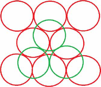
Number of contacting spheres in hexagonal geo- metry. Red and green spheres represent first and second successive layers
The filler volume fraction of metal particle P can be written as
Assuming a linear relationship43):
where Pm is the maximum packing fraction of the filler in the matrix.
Rearranging the two equations, we get:
For a random mixture of spheres, Cp = 1.5, N = 6, and Pm = 0.637. Therefore, Pc becomes to 0.159. Later Jantzen proposed44):
At the percolation threshold, we have:
For a random network of sphere, Pc becomes to 0.305, which corresponds to the critical volume fraction (Vc) of the filler particles. For irregular fillers with a completely random distribution, the critical value of Pc is assumed to be the same as that for spherical ones43-45).
6.2 Bonding mechanism
Epoxies have long polymeric chain made with large molecules that form a cross-linked 3D structure with good strength, low shrinkage, and high elastic moduli. The bonding mechanism of the epoxy solder pastes, therefore, involves mechanical interlocking of the joint brought about by the cross-linked polymer chains. Therefore, the bonding primarily depends upon the surface morphology of the joint rather on material composition. The sequence of bonding is shown in the Fig. 3.

Joining process of solder and epoxy-based solder.
At the curing temperature, the polymer chains get entangled among one another and causes the viscosity to increase thus making a robust bonding. Sufficient curing time is needed to further distribute the heat at the interface joint and penetration of the polymer molecules over the surface. As soon as the epoxy cools, viscosity rises drastically and mechanically bonded structure adheres. Due to a high viscosity, the joint is well protected from the outside environment and is relatively stable. The general sequence of bonding components with epoxy-based solder paste is similar to solder joining. The following Table 3 shows the differences between the joining process of epoxy solder paste and conventional solder pastes.

Epoxy solder paste and conventional solder paste joining process
Great care is needed for curing of epoxy-based materials at the desired temperature, otherwise epoxy may not fully cure and joint may fail. The conductivity of the epoxy matrix can be improved by using certain types of conductive or inert filler particles. However, nanoparticles tend to aggregate after reflow and their use is limited46,47).
7. Future perspectives and summary
In this review, we overviewed epoxy-based solder pastes for application in surface mount devices, flexible and automotive electronic devices in comparison to the conventional solder pastes. The studies on epoxy solder pastes are likely to rise in the future due to their advantages such as cost-effective and their increased demand in flexible circuits. However, certain drawbacks exist like cold storage needed for storing epoxy solder pastes, and most importantly, the inability to rework the joint. Therefore, the epoxy-based solder pastes are needed to be developed to cut down the cost of expensive nano- fillers used in solder powders. Epoxy-based solders have been also applied in automotive electronics and is a promising alternative for improving the reliability of auto- motive components. Therefore, this review can be a guideline for further research on the application of epoxy solder pastes in future electronic packaging.