Effect of Process Parameters and Nugget Growth Rate on Liquid Metal Embrittlement (LME) Cracking in the Resistance Spot Welding of Zinc-Coated Steels
Article information

Abstract
Although the influence of weld process variables on LME cracking was known to be significant, limited studies have been conducted on the effect of process variables with systematic approaches in the equivalent nugget growth behavior and heat input. This study aimed to identify the effect of weld process variables on LME sensitivity with the equivalent nugget diameter and underlying mechanism with induced tensile stress for cracking. Among the welds with equivalent nugget diameters in the combination of different welding current and time, higher LME sensitivity was observed with the high welding current and short welding time combination than that with the low welding current and long welding time combination for the equivalent nugget diameter. Because a high current and short time combination resulted in faster weld nugget growth than the low welding current and long welding time combination, it rapidly increased the surface temperature along with the cooling from the electrode. These combined effects induced a higher thermal gradient and thermally induced tensile stress on the weld surface, satisfying the conditions of the LME cracking. The simulation results also confirmed that the critical weld cycle time of the LME cracking (tc), which is the cross point between the nugget growth diameter and a contact diameter of the electrode, could be different with the combination of the weld process variables with the equivalent weld nugget size. Therefore, tc can be applied for the sensitivity index of LME cracking of the resistance spot weldment considering complex weld variables.
1. Introduction
To comply with the strict emission and fuel efficiency regulations, development of lightweight automobiles using advanced high strength steels is growing, and zinc (Zn) coating is done to improve the corrosion resistance of these steel sheets. The Zn-coated advanced high strength steels exhibit cracks of liquid metal embrittlement (LME) due to increase of tensile stress from heating, cooling, and melting of Zn during resistance spot welding or hot stamping process1,2). Various issues arise regarding the quality of welding and strength reduction of resistance spot welding joints due to LME cracks3-5). LME cracks occur when the following three conditions exist: 1) liquid metal, 2) tensile stress environment, and 3) sensitive microstructure. Murugan et al6). studied the LME crack mechanism by conducting cryogenic impact test and analyzing ruptured surface of the LME cracks. Most cracks were intragranular cracks, and the liquid Zn penetration was along the prior austenite grain boundaries (PAGB). Also, the crack tip contained remnants of liquid Zn. So, there reported that the mechanisms of Zn-induced LME cracks involve the penetration of liquid Zn along the grains that reduce the surface energy and lower the atomic bonding strength.
To better understand the LME cracks, studies reported the effects of the microstructures of the material of interest, Zn coating layers, and variables related to resistance spot welding. First, the sensitivities related to LME cracks were compared by performing high-temperature tensile tests to investigate the factors affecting LME cracks such as the material type, and effect of microstructure for steels with similar microstructures as well as the introduction of alloying elements such as silicon (Si)7-11). Here, Bhattacharya et al8). reported that the LME sensitivity was low for dual phase (DP) steel, which consisted of ferrite and martensite, since the PAGB fraction, which increased the likelihood of LME crack, was low and inconsistent. Also, as the base metal Si alloy content was increased, Kalashami et al.10) reported that heat input amount was increased due to increase in resistance for resistance welding. Hong et al.11) claimed that the LME crack sensitivity increased due to higher probability of contact between liquid Zn and parent material by hindering the formation of α -Fe(Zn) layer at the boundary between the base metal and Zn coating layer. Secondly, in terms of the effect of Zn coating layer, Kim et al.12) investigated the effect of resistance spot welding variables on alloying of the coated layers, and Murugan et al.13) compared the high-temperature tensile test results at various temperatures and durations. These studies showed that the LME crack sensitivity was affected by the α-Fe(Zn) layer thickness or damage. Also, depending on the Zn coating methods, Ashiri et al.14) compared the LME crack sensitivities of galvanized (GI), Galva-annealed (GA), and electrogalvanized (EG) Zn coatings. They reported that the LME crack sensitivity was lowest for EG coated steel plates due to the formation of α-Fe(Zn) layer from alloying of the coated layer during high-temperature processes and resistance spot welding. Thirdly, the changes in LME crack sensitivity depending on the variables related to resistance spot welding (welding current, time, and electrode force etc.) were reported. Ling et al.15) measured the LME crack sensitivities using Taguchi experimental methods while controlling the individual process variables. Here, the welding current, electrode force, welding time, and holding time affected the LME crack in this order, but there was a lack of explanation on the individual variable effect. Also, Siar et al.16) compared the individual effect of electrode arrangement, holding time, electrode force, and welding time and reported that the misalignment of the electrode, short holding time, low electrode force, and longer welding time increased the sensitivity of LME cracks. However, there was no discussion on the cause-effect relationship for each variable and correlation effect between the variables. Studies12,17,18) showed that higher welding current and longer welding time increased the LME crack sensitivity as tensile stress increased due to higher heat input. However, Choi et al.19) reported that, given the same nugget diameter, the LME crack sensitivity increased as electrode force decreased when the electrode force and welding time were controlled. This was due to the reduction of surface area from the decreased cooling effect. Other similar studies reported the effect of single variable related to welding, but did not offer systematic analysis of the cause-effect relationship between the process variables and the LME crack sensitivity or the effect of interrelated variables on LME cracks given equivalent heat input conditions.
Among the resistance spot welding process variables, the variation of nugget growth rate according to each individual variable such as welding current, welding time, and electrode force appears to be large, but most of the previous studies have not been compared them under the equivalent heat input condition. There are limitations in evaluating the effect of a single variable on LME crack susceptibility, and most of the previous studies reached limited conclusions. Thus, this study investigated the existence of LME crack for equivalent nuggets obtained from the lobe curve, which represents the optimal resistance spot welding conditions based on welding current and welding time. The study goal was to obtain a regression equation that predicts the LME sensitivity under complex process conditions, to identify the factors contributing to the LME cracks, and to understand the cause-effect relationship between these factors and tensile stress development necessary for LME cracks. Also, this study aimed to identify the differences of LME crack sensitivities caused by complex process conditions such as welding current and welding time by analyzing the correlation between the nugget growth, the electrode and sheet contact behavior.
2. Methods
The materials used in this study were a 1.2 mm thick GA coated manganese steel (Fe-4Mn-0.4Si-0.2C) and two sheets of 1.5 mm thick GI coated mild steel (Fe-0.08Mn-0.1Si-0.002C). This study focused on the manganese advanced high strength steel with the following mechanical properties: tensile strength of 780 MPa and ductility of 27 %. Two mild steel sheets were used to obtain high LME crack sensitivity by achieving nugget diameter larger than 6.5 mm from increasing the heat input during the resistance spot welding process6,16). A Cu-Cr electrode with 6 mm diameter electrode tip and dome shape following the ISO standard F1-16-20-40-620) was used. To obtain the lobe curve that represents the optimal welding conditions for resistance spot welding, various welds were produced under different conditions, with five welds produced per condition. Each condition consisted of different welding times (167, 250, 333, 417, 500, 583 ms) with different welding currents at 0.5 kA increments starting from the minimal nugget diameter (4√t) current to expulsion limits current (Table 1). The minimal nugget diameter current was defined as the current that satisfied the 4√t conditions from measurement of button diameter using vernier calipers via the peel test. The expulsion limits current was defined as the current that caused expulsions in at least three out of five welds. The expulsion was determined visually as well as when a sudden decrease was observed in the dynamic resistance curve. To verify the repeatability, three additional welds were performed for each welding condition.

Process parameters of resistance spot welding to construct weld lobe
The formation of nuggets and cracks were observed using stereo microscope and optical microscope (OM), and the nugget diameter and crack length were measured using Image Pro software. Further base metal microstructure and coating layer characterization was done using scanning electron microscope (SEM), SEM-back scattered electron (BSE), and energy dispersive X-ray (EDS) equipment at the Core Research Support Center for Convergence Components and Materials, Dong-Eui University. Also, SEM-EDS and electron back scatter diffraction (EBSD) equipment were used to analyze the observed crack characteristics. Since cracks occur and propagate differently depending on the stress behavior and experienced temperature at the contact between the sheet and electrode during resistance spot welding process, the contact between the electrode and sheet was divided as shown in Fig. 1, as demonstrated by Murugan et al.21) The study focused on the crack in Location C where there was no contact with the electrode which caused large cracks and greatly reduced the strength of welds.

3. Results
3.1 LME crack analysis
Fig. 2 shows the SEM and OM analysis of the GA coated manganese steel’s base metal and coating layer. The OM microstructure of the base metal in Fig. 2(a) illustrates the elongated grains with size less than 5μm due to rolling process, and the SEM images shows the presence of bainite and some retained austenite in the pearlite matrix (Fig. 2(b)). The existence of the retained austenite was reported to be sensitive to LME cracks due to increase in tensile stress from the high heat expansions and contractions, according to Jung et al.18) The SEM-BSE and EDS results indicated that the base metal has about 6.0 μm thick GA coating layer, and most of the coating layer and the surface consisted of γ and δ, respectively, due to heat treatment during the alloying process (Fig. 2(c)).
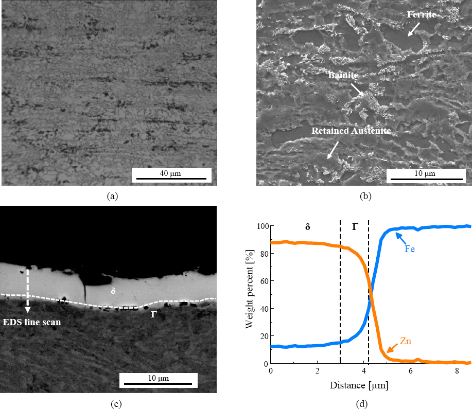
(a) OM and (b) SEM image of etched base material of medium manganese steel, (c) SEM-BSE image and EDS result graph of GA coating layer
The cross section of the cracked spot weld (Fig. 3(a)) and the enlarged image of the cracked location in the surface (Fig. 3(b)) show that the crack occurred in the coarse grain heat affected zone (CGHAZ) and Location C zones where there was no contact between the electrode and base metal, as shown in Fig. 1. To verify the existence of LME crack due to Zn (Fig. 3), the distribution of Zn in “A” areas of the cracked surface is shown in Fig. 4(b) obtained using the SEM-EDS mapping (Fig. 4(a)). Zn was continuously detected along the crack path from the start, and these cracks were most likely LME cracks induced by liquid Zn, according to Bhattacharya et al.7) who reported that the LME cracks propagated along the PAGB where liquid Zn penetrated. Also, EBSD analysis of the correlation between the grain misorientation angle and grain orientation was conducted at the tip of the crack (“B” area) shown in Fig. 4(a) to understand the crack characteristics. The inverse pole figure (IPF) map shows the grain orientation around the crack surroundings, and the average grain size was 0.9 µm along the crack path and has grown about 0.3 µm of grain compared to the base metal. Also, the misorientation angle, which is a characteristic of LME cracks induced by liquid Zn, was investigated. Since the key LME crack gap was more than 5 µm, there was a limitation for measuring the nearby intergranular misorientation angles. Thus, grain misorientation angle for the 2nd LME crack zone for “C” area was measured as shown in Fig. 4(c). Referring to the results in Fig. 4(d) , the progression of LME cracks along the high angle grain boundary (HAGB) (larger than 15˚) was observed for the entire 2nd LME crack path. HAGB was reported to be easily affected by the penetration of Zn due to the relatively excess energy and volume resulting from the low atomic filling rate22,23). From the studies of Murugan et al.6) and Bhattacharya et al.7), the orientation difference between the left and right side of the crack was measured to report the progression of grain boundary characteristics. Also, similar to the analysis results, these studies reported high probability of the spread of crack along the PAGB, which is also HAGB, or the interface of the retained austenite. The SEM-EDS and EBSD analysis of the cracks are consistent with the previously reported LME crack characteristics, and the cracks in the resistance spot welding joints of the GA coated manganese steel were LME cracks. In the previous study, the LME cracks were also found in Location C12,21)
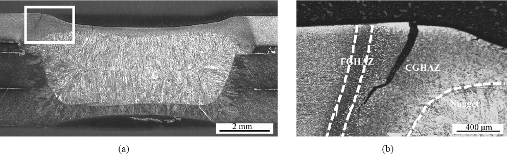
(a) Weld cross section etched image of crack occurrence sample, and (b) Magnified image of area A. (Sample ID: C-1)
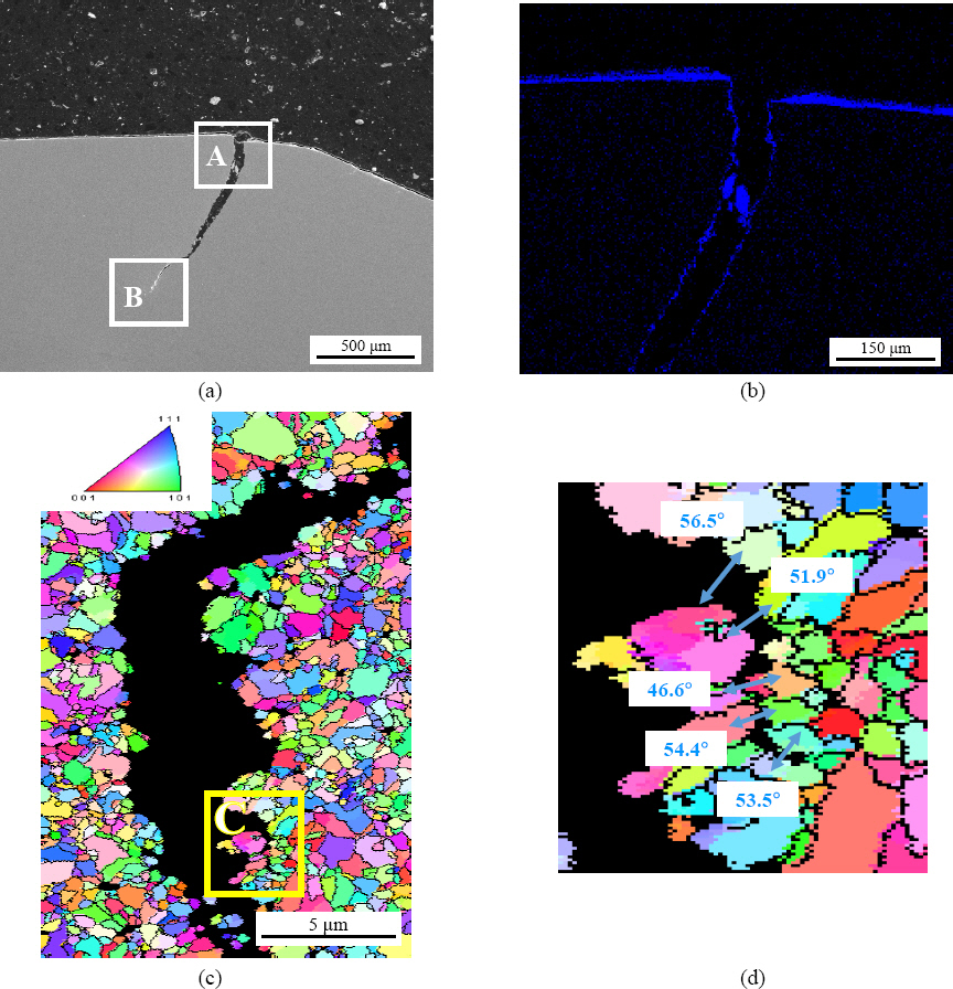
Analysis of the characteristics of crack that occurred during RSW. (a) SEM image, (b) Zn element EDS mapping image of area A (Zn: Blue color), (c) EBSD crack tip IPF map in area B and (d) Misorientation angle between the grain of the secondary crack at the crack tip. (Magnified image of area C) (Sample ID: C-1)
3.2 Sensitivity of LME Cracks based on welding variables
As explained in the Methods section, the lobe curve was obtained and shown in Fig. 5(a). Fig. 5(b) illustrates the contour line indicating the combinations of the welding current and welding time that generate equivalent nugget diameters. The combinations that caused or did not cause LME cracks are identified in Region A of Fig. 5(a). The “Contour line A,” “Contour line B,” and “Contour line C” had nugget diameters of 7.3, 7.7, and 8.0 mm, respectively. The welding conditions along the contour line of equivalent nugget diameter show that the conditions that caused LME crack (yellow) and those that did not cause crack (blue) exist, and the cracks occurred in about 25% of the region of the total weldable areas. Also, LME crack was observed only in the welding conditions with high welding currents of 9.0 and 9.5 kA among the four process conditions, according to the contour line of equivalent nugget diameter at 7.3 mm (Contour line A)
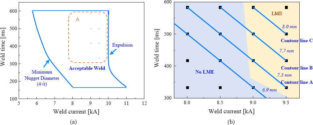
(a) Lobe curve of resistance spot welding for medium manganese steels, (b) LME cracking area and similar nugget diameter line in area A. (Fixed electrode force of 3.0 kN, LME = Location C LME crack)
To compare the LME crack status for different conditions, the crack sensitivities were computed using Eq. 1 and organized in Table 2 for conditions that generated nugget diameters larger than 7.3 mm. The crack sensitivity was defined as the ratio between the product of the sum of LME crack lengths and the number of cracked samples and the total number of samples. The total number of samples was 8 (=5 repetitive welds + 3 additional welds for reproduction of results). Also, the range of LME crack sensitivity was at most 9.6 and at least 0.0, and all the 8 samples showed crack at the maximum value of 9.6, which was also the crack sensitivity that caused penetration of sheets at all thicknesses (If the thickness of material is 1.2 mm, 1.2 is substituted). The minimum sensitivity of 0 was when there was no crack for all the 8 samples.

Length, number, and sensitivity of LME cracks for corresponding nugget diameter with various welding conditions
The effects of welding current and time on the crack sensitivity are compared in Fig. 6. Fig. 6(a) shows that as the welding current increased for different welding times (333, 417, 500, and 585 ms), the crack sensitivity also increased. Comparing the welding time of 417 and 500 ms, the increase in crack sensitivity with increase in welding current from 9.0 to 9.5 kA at 500 ms was about four times higher. Also, Fig. 6(b) depicts the increasing trend in crack sensitivity for longer welding time for welding current of 9.0 kA and 9.5 kA, and there was a sharper increase in crack sensitivity values for 9.5kA than 9.0kA as welding time increased.
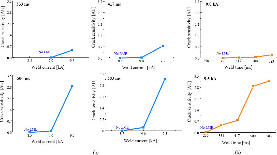
(a) LME crack sensitivity with weld current at weld time of 333, 417, 500 and 583 ms, and (b) LME crack sensitivity with weld time at weld current of 9.0 kA and 9.5 kA, respectively
The crack sensitivities for various nugget diameters in the contour line for equivalent nugget diameter (contour line A, B, C) (Fig. 5(b)) are shown in Fig. 7. For the contour line with equivalent diameter of 8.0 mm (contour line C), the crack sensitivity values were 2.862 and 0.203 for C-1 and C-2 welding conditions, respectively. In this study, among the conditions that produced equivalent nugget diameters, higher welding current and shorter welding time produced higher crack sensitivity. Comparing the nugget diameters of 7.3, 7.7, and 8.0 mm, as the nugget diameter increased, the amount of increase in crack sensitivity (ΔS in Fig. 7) per increase of welding current was higher. Also, comparing the A-1 and A-3 conditions for nugget diameter of 7.3 mm, higher welding current and short welding time in A-1 condition caused LME crack (crack sensitivity = 0.452) while the lower welding current and longer welding time in the A-3 condition did not cause LME crack (crack sensitivity = 0). Thus, even for conditions generating similar nugget diameters in the weldable areas, the welding current and welding time affected the generation of LME cracks.
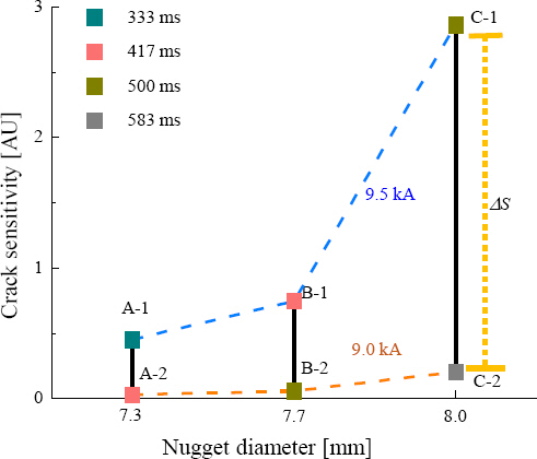
LME crack sensitivity with a combination of weld time and current combinations at nugget diameter. (7.3 mm, 7.7 mm and 8.0 mm)
4. Discussion
4.1 Effect of welding current and time on LME cracks
Based on the results in Fig. 5 and Fig. 6, as welding current and time increased, the crack sensitivity increased, and there was higher increase in crack sensitivity per increase in welding time for 9.5 kA than 9.0 kA welding current (Fig. 7). Also, there was higher increase in crack sensitivity as the nugget diameter increased under the conditions with welding time of 500 ms (B-2, C-1) than 417 ms (A-2, B-1). This increase in LME crack sensitivity could be due to the increase in thermal stress caused by the increased heat input from the increase in welding time and current and larger nugget size.
Since the LME crack sensitivity greatly varies depending on the process variables, the heat input can be calculated from the values of the welding current and time using the Joule’s heat equation. Assuming identical heat input for the nugget diameter (ND), the LME crack index can be obtained using Eq. 2, 3 for each current value.
For different materials and thicknesses, there may be limitation since LME crack sensitivity may differ depending on the maximum available heat input. Thus, additional research is needed to develop a more standardized method that normalizes the LME crack index holistically considering the different material type, thickness, etc.
Deeper understanding of the LME crack sensitivity is needed by analyzing the correlation between the crack generation, tensile stress and resistance spot welding process variables. Using similar approaches, Kim et al.12) and Murugan et al.21) reported the mechanism explaining the relationship between the LME crack propagation and increase in tensile stress during the resistance spot welding process. To analyze the changes of the tensile stress for different welding currents and times, a commercial simulation program (SORPAS®) was used (Fig. 8, 9). Fig. 8 shows the simulation results of the increase in nugget diameter for different welding times as well as the contact diameter of the interface between the electrode and surface (E/S contact diameter, E/S; Electrode and surface interface) for different welding currents. During the early welding time for each current condition in Fig. 8(a), the E/S contact diameter increased from 4.0 mm and plateaued at 6.0 mm along the electrode tip diameter for different electrical current time, and the nugget diameter grew from 5.6 mm to 7.3 mm for electrical current range between 7.5kA and 9.5 kA. For welding current above 8.5 kA, the nugget diameter during the current flow exceeded the E/S contact diameter, and the critical weld cycle time (tc) of the LME cracking when the two curves met were 295 ms and 214 ms for electrical current of 8.5 kA and 9.5 kA, respectively. For each welding current after tc, the cooling effect from the electrode contact was limited as the molten nugget rapidly grew, so there was a large thermal gradient on the surface, indicated by the “A” areas of Fig. 8(a) and Fig. 8(b). This thermal gradient that caused increase in tensile stress on the exteriors of the electrode contact was also reported by DiGiovanni et al.24), and the increase of tensile stress that caused the crack in this study was continuously observed in Fig. 8(c). Thus, we determined that, during the resistance spot welding process and assuming liquid Zn existed, the generation of tensile stress after tc caused the LME cracks. As welding current increased, the current flow became faster after tc, which induced faster nugget growth due to higher welding current. This suggests that the higher increase in heating rate was caused by the higher welding current, and the cracks formed due to higher tensile stress and larger thermal gradient. Also, from the simulation results, for higher welding time at a constant welding current of 9.5 kA (Fig. 9), the critical area was enlarged, and tc was identified for welding time longer than 250 ms (Fig. 9(a)). As shown in Fig. 9(b) and 9(c), the tensile stress was only generated in the condition where there was an increase in thermal gradient and crossing that occurred above 214 ms. To summarize the simulation analysis, as the welding current and welding time respectively increased, the decrease in the weld cycle time for the occurrence of tc and the increase in the size of the critical area after tc led to an increase in the LME crack sensitivity.
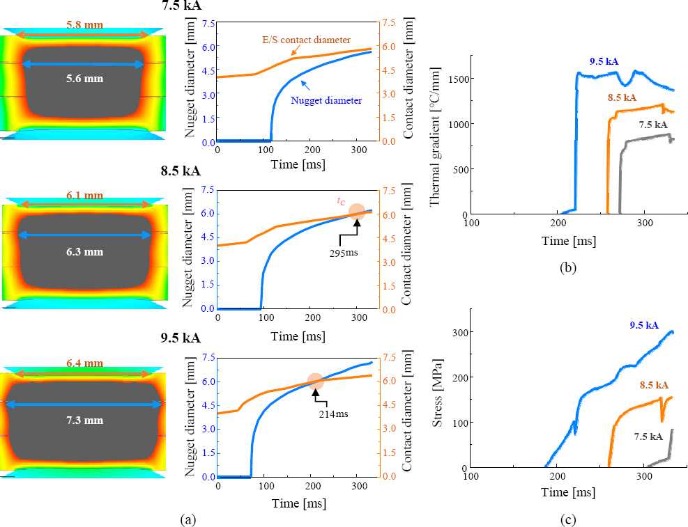
Simulation results, (a) Changes in behavior of nugget diameter and contact diameter, (b) Thermal gradient and (c) Stress depending on weld current. (Fixed weld time is 333 ms)

Simulation results, (a) Changes in behavior of nugget diameter and contact diameter, (b) Thermal gradient and (c) Stress depending on weld time. (Fixed weld current is 9.5 kA)
4.2 LME crack sensitivity for conditions generating equivalent nugget diameters
Under the identical heat input conditions, the welding current and time were compared based on conditions generating equivalent nugget diameters to understand their effect on LME crack sensitivity. The LME crack sensitivity was higher for conditions with relatively higher welding current and short welding time as shown in Fig. 7. Thus, the combinations of welding current and time for generating identical nuggets showed similar amount of heat input, but there was a difference in thermal gradient on the nearby areas of the LME crack on the sheet surface based on the heat loss and conductivity. In general, for the resistance spot welding, the information regarding the heat input can only be verified using indirect methods such as measuring the nugget diameters or characterizing dynamic resistance curves25). Fig. 10 is a graph showing the dynamic resistance obtained from the voltage and welding current data relevant to the heat loss of the A-1 condition (9.5 kA/ 333 ms) that caused LME crack and A-3 condition (8.5 kA/500 ms) that did not cause the crack for nugget diameter of 7.3 mm. From the curves, the slopes of A-1 and A-3 were 0.22 and 0.17, respectively, from the melting point (β-peak) and the end of current flow. Since the slope changes of the resistance in A-1 was high, the nugget formation was quick, and since the reduction of resistance was slow for A-3, the nugget growth was slow. The cross section of welding joints for A-1 and A-3 are shown in Fig. 11(a) and (b). The nugget diameter and area of A-1 and A-3 were identical (7.3 mm and 19 mm2), but the fusion boundary (dotted line) of each nugget was different. For A-1 condition, the upper portion of the sheet surface and the melted edge distance (arrowed areas in Fig. 11(a) and (b)) were smaller, and it is predicted that the tensile stress due to the increase in thermal gradient and sheet surface temperature would be higher. Thus, dissimilar process conditions caused the difference in tensile stress and thermal gradient near the LME crack area, and the LME crack sensitivity differed based on the process variables given the conditions producing equivalent nugget diameters. Also, the heat input amount, a factor that affects the tensile stress from the surface temperature, was known to affect the LME crack sensitivity26). However, if the heat input amount is similar for identical nugget diameters, the difference in surface heat output greatly affected the LME crack, and this can explain the differences in LME crack sensitivities depending on the sheet thickness, nugget growth, and electrode shape27), all of which affect the surface heating in resistance spot welding28).
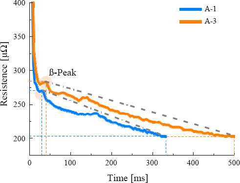
Dynamic resistance curve of A-1 and A-3 with same nugget diameter 7.3 mm

Nugget image under conditions (a) A-1 and (b) A-3 with same nugget diameter
To verify the effect of the temperature difference between the surface and nugget exterior for different process combinations, the tensile stress and thermal gradients of LME crack locations were compared through simulation that computed tc and applied mechanisms of nugget growth and electrode contacts. Fig. 12(a) depicts the 4 combinations of welding current and welding time (S1, S2, S3, and S4) for nugget diameter of 7.3 mm, and Fig. 12(b)~(d) show the changes in tensile stress, thermal gradient, nugget diameter, and E/S contact area for each combination. Fig. 12(b) compares the changes in E/S contact diameter and nugget diameter for different process conditions, and the rapid nugget growth due to fast heating rate was verified for high welding current in S-4 condition. For S-1 condition, the nugget growth was slower due to slower heating rate from relatively low welding current. Due to these differences, the tc, i.e., when the nugget diameter and the E/S interface diameter coincided, was shifted forward, causing higher thermal gradient (Fig. 12(d)) as well as high tensile stress (Fig. 12(e)) in S-4 condition. Also, the S-1 condition that had lower welding current delayed the tc, and the thermal gradient and tensile stress were both reduced (Fig. 12(d), (e)). After tc, the completion time of welding was increased, causing an increase in thermal gradient and tensile stress. However, if tc is shifted earlier, there is an increase in thermal gradient and tensile stress in a short time span due to reduction in cooling effect and higher heat input following the Joule’s heat equation given higher welding current. Also, looking at Fig. 13 which illustrates the formation and growth of nuggets for different welding time, molten nuggets form in a short time span at fast heat input rate for S-3 and S-4 conditions with high welding current, and the nugget fusion lines are formed near the surface due to reduction of cooling effect. However, the molten nugget formation was delayed due to slower heat input rate and low current for S-1 and S-2, causing formation of nuggets relatively far from the surface. When compared to other conditions with high welding current and rapid temperature changes, this caused higher thermal gradient and tensile stress (Fig. 12(d), (e)), leading to higher LME crack sensitivity. Thus, for equivalent nugget diameters, the increase in welding current caused higher LME crack sensitivity than the increase in welding time.
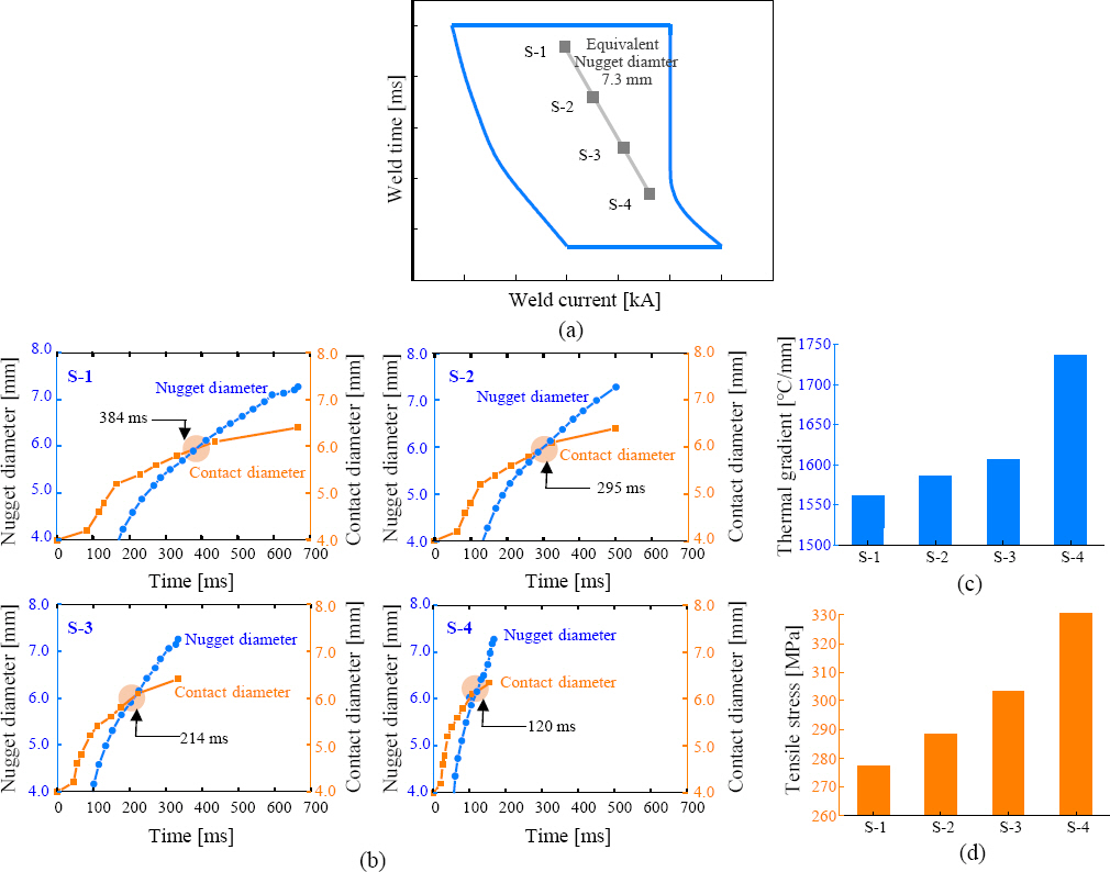
Simulation results for (a) A 7.3 mm nugget diameter on lobe curve. Comparison graph of (b) Contact and nugget diameter, (c) Peak thermal gradient and (d) Peak tensile stress behavior according to conditions

Simulation of nugget growth according to welding time and current at the same nugget diameter (7.3 mm)
4.3 Derivation of critical nugget diameter for LME crack formation
Looking at the contour line with equivalent nugget diameter of 7.3mm (contour line A) in Fig. 5(b), conditions that formed crack (A-1, A-2) and conditions that did not form crack (A-3, A-4) both existed, and there were no LME crack formations for conditions with nugget diameter less than 7.3 mm. The LME crack forms only when there is the presence of liquid metal, enough tensile stress, and microstructure sensitive to LME crack1,2), so given an identical material’s microstructure, the liquid Zn fraction, and the coating material, the sheet surface tensile stress increases with increasing nugget diameter14). Thus, one can predict that a nugget diameter of 6.9 mm was the critical nugget diameter that did not cause the LME crack. Extrapolating this idea via simulation (Fig. 12), the S-3 and S-4 conditions in this study were conditions that caused LME crack formations, while S-1 and S2 conditions did not form LME cracks due to low tensile stress albeit tc existed.
In general, as nugget diameter increased the LME crack sensitivity increased (Table. 2), but higher LME crack sensitivities were observed for conditions with small nugget diameter (A-1) than larger nugget diameter (B-2) at higher welding current. This may be due to the slow surface cooling characteristic and rapid nugget growth induced by the welding current. Based on this mechanism, if LME crack sensitivity condition, which is identical to LME crack formation sensitivity index (0.452) for A-1 condition (welding current of 9.5kA and nugget diameter of 7.3 mm), is derived in welding current 9.0 kA using Eq. (2), the identical LME crack index is derived under the condition with 667 ms welding time and 8.2 mm nugget diameter. Thus, as welding current is reduced, larger nugget diameter and longer current flow are needed.
Also, Ashiri et al.14) investigated the critical nugget diameters for three different coating methods (GI, GA, EG) for twinning induced plasticity (TWIP) steel, which was mostly made of austenite. While there were some differences depending on the coating method, below a certain nugget diameter, the LME crack was not formed, and the GA coated TWIP steel was reported to have a critical nugget diameter of 6.22 mm. Comparing the critical nugget diameters, this study detected the differences of critical nugget diameters that depended on the material type, grain energy within microstructures, coefficient of heat expansion, and differences in tensile stress from process variables.
5. Conclusion
This study investigated the effect of resistance spot welding process variables on LME crack sensitivities of Zn coated advanced high strength steel.
1) Among the weldable areas, LME cracks occurred at high welding current and long welding time. These cracks constituted about 25% of the conditions were cracked areas.
2) After analyzing the effect of welding current and time on the LME crack, higher welding current and longer welding time increased the LME crack sensitivity, inducing larger nugget sizes due to higher heat input.
3) After analyzing the combinations of factors affecting LME crack sensitivity, i.e., welding current and time, high welding current and short welding time displayed higher crack sensitivity than low welding current and long welding time. This trend was more pronounced for nugget diameters of 8.0 mm than 7.3 mm, noted by the larger increase gap in crack sensitivity.
4) After analyzing the simulation results of increase in nugget diameter and the changes in the contact diameter of the interface (E/S) between electrode and sheet for different welding times and currents, the tensile stress that is required for LME cracks was formed at critical weld cycle time (tc) when the curve for nugget diameter surpassed the curve for E/S contact diameter. Also, as the welding current and time increased, LME crack sensitivity increased as the tc was reduced and the size of critical region after tc increased.
5) For conditions creating equivalent nugget diameter, extremely large thermal gradient was formed on the surface due to the reduction of cooling effect and the growth of molten nugget at high welding current, heating rate, and heat input. Thus, tc occurred earlier, causing higher thermal gradient and tensile stress. Thus, as welding time increased, greater thermal gradient and tensile stress behavior was observed. These gradient and stress behavior affected the LME crack sensitivity due to increase in tensile stress and thermal gradient caused by increase in heating rate from higher welding current.
Acknowledgements
This study was funded by the Ministry of Trade, Industry, and Energy’s material parts technology development project “Development of car body part utilizing AlSi coated hot press forming steel (Project Number: 20013403)” and the Ministry of Trade, Industry, and Energy’s Industrial technology Alchemist project “Al based supercritical materials discovery (Project Number: 20012196)”.