


1. Introduction
The increasing application of high-strength and lightweight materials has led the automotive industry to reconsider the materials joining processes. Manufacturers are applying a variety of lightweight materials to chop down vehicle weight, thereby minimizing fuel consumption and emissions1). Consequently, the development of aluminum alloys, high-strength steels, and fiber-reinforced plastics has been accelerated in recent years2). However, the joining of these multi-materials is troublesome because of their unlike thermal and electrical properties. Thus, mechanical fastening technologies have attracted increasing interest.
Self-piercing riveting (SPR), a mechanical fastening technique, has become a prominent joining process in the automotive and aircraft industries. SPR forms a mechanical interlock between two or more sheet materials by driving a semi-tubular rivet through the top material and then spreading into the bottom material with the assistance of a counter-die on the other side. The sheet deforms inside the die and forms a button on the underside of the bottom material. SPR process has several advantages including high joining speed and automation flexibility3). When compared to traditional riveting, SPR results in higher joint strength and repeatability of the joining process. SPR is capable of joining multiple layers of materials of varying thicknesses4). Unlike conventional welding processes, SPR joints do not involve fusion between the joining materials. SPR joints have comparable static strength and better fatigue behavior than spot welds5). While SPR is widely used to join aluminum alloys6,7) in the automotive industry, it can also be applied for joining steel-aluminum8) and CFRP-aluminum9-11).
SPR has the ability to join a variety of dissimilar materials. Zhang12) identified the feasibility of SPR process for joining steel to aluminum alloys. SPR produces better static and fatigue strengths than conventional spot welds between steel and aluminum13). Ma et al.14) demonstrated the joinability of aluminum alloys with different gauges to mild steel sheets. Kam et al.15) illustrated the feasibility of SPR joints between vibration-damping steel (consisting of two steel sheets separated by a viscoelastic adhesive polymer layer) and an aluminum alloy. Zhang et al.16) observed that the strength of the steel significantly influenced the strength of steel/aluminum SPR joints. Abe et al.8) presented that arranging steel as the top sheet and aluminum alloy as the bottom sheet showed better joinability compared to the opposite orientation. Sun17) also investigated the influence of riveting direction on joint strength of steel to aluminum alloy, and the results showed that the joint with aluminum alloy as the bottom sheet had higher strength than the reversed orientation with steel as the bottom sheet in lap shear. Currently, carbon fiber reinforced polymer (CFRP) is replacing the heavy metals where lightweight is the first priority. Chen et al.18) demonstrated the joinability of CFRP to aluminum alloys SPR joint with a reasonable joint strength. However, large deformations in SPR operation can lead to cracking and fracture of the CFRP composites because of their lower ductility than metallic materials19). Consequently, the CFRP should be placed on the top side of the SPR joint because the top material experiences comparatively less deformation than the bottom material20).
The results in literatures identify that the sufficient ductility of the bottom material is a general requirement for better performance of SPR joints. While the application of SPR joints for various similar and dissimilar materials combination, i.e., aluminum/aluminum, steel/ aluminum, and CFRP/aluminum, is growing rapidly, aluminum sheet is kept as bottom side material. However, the joint formation and mechanical behavior of joints of various top sheet materials with bottom aluminum alloy have not been systematically investigated in previous studies. The present study focused on the effects of the top sheet material on the joint formation characteristics, joint quality and mechanical behavior of SPR joints.
2. Materials and methods
2.1 Materials and SPR joint preparation
The materials used were dual phase (DP) 590 MPa steel sheets, aluminum alloy sheets with pre-treatment (Al5052-H32), thermosetting CFRP sheets, and 38B2 boron steel self-piercing rivets. The CFRP sheet was prepared using epoxy infusion resin (MGS┬«RIM) and 5-┬Ąm-diameter carbon fibers, which contained seven unidirectional prepregs with 0┬░ and 90┬░ orientations. A hydraulic shearing machine was used to cut the steel and aluminum sheets, while a water jet was used to cut the CFRP sheets. The mechanical properties of the 590DP steel, Al5052-H32 aluminum alloy, CFRP sheets, and rivet material used in the specimensŌĆÖ preparation are presented in Table 1. Sheet materials with various thicknesses were chosen for this study based on their extensive applications in the automotive industry.
Table┬Ā1
Mechanical properties of sheet materials and rivet material used for the SPR joints
To achieve higher static strengths, the joints were prepared with the maximum interlock distance, minimum head height (close to zero), and a minimum thickness of the remaining bottom material of 0.2 mm, as suggested by Li21). The rivet parameters (strength, hardness, length, and diameter), die parameters (type, diameter, and cavity depth), and setting force were determined through a series of trial experiments. Dies with a flat bottom and vertical sidewalls were used. The same die profiles with varying die diameters and cavity depths were adopted to improve the joint quality. An electroplated Zn-Ni coating was used to the steel rivets. The specimens were prepared using an electro-hydraulic riveting equipment (B├¢LLHOFF/RIVSET┬« Gen2). To obtain the recommended joint quality (particularly, a head height close to zero and interlock distance of minimum 4.0 mm), numerous trial tests were conducted to select the appropriate riveting condition. Table 2 presents the parameters of riveting condition for steel/aluminum, CFRP/aluminum, and aluminum/aluminum joints. Aluminum alloy hereinafter referred to as ŌĆ£AlŌĆØ (e.g., steel/Al, CFRP/Al, and Al/Al). For the experimental evaluation, at least five specimens were selected for each type of materials combination from a large number of joints.
Table┬Ā2
Process parameters for steel/Al, CFRP/Al and Al/Al joints
2.2 Lap-shear and cross-tension tests of SPR joints
Lap-shear and cross-tension tests were executed using a KSTM tensile test machine. A strain rate of 5 mm/ min was applied at the ambient temperature. The geometry and dimensions of the lap-shear and cross-tension specimens are shown schematically in Fig. 1.

2.3 Metallographic characterization of SPR joint cross-sections
To eliminate any distortions in the SPR joint during cutting, the specimens were cut perpendicular to the loading direction using a high-precision blade (diamond- wafer). The sectioned specimens were mounted in unsaturated polyester resin for optical microscopic examinations. Following the mounting procedure, the specimens were prepared using metallographic techniques such as grinding wheels with varying grit sandpapers and diamond suspensions. The specimens were analyzed using an optical microscope (Olympus BX51M), field emission scanning electron microscopy (FE-SEM; JEOL JSM-7200F) and a stereoscope (Leica EZ4 HD) at the Converging Materials Core Facility, Dong-Eui University.
2.4 Finite element analysis of SPR joints
A commercial software (ABAQUS/Explicit) for finite element analysis was used to perform the simulations of the riveting process and lap-shear test of SPR joints. To improve the calculation efficiency, an axisymmetric boundary condition was applied. To impede simulation termination because of large element distortion, arbitrary Lagrangian-Eulerian (ALE) mapping was used to the sheet materials as a re-meshing technique. Zhong et al.22) reported that the ALE coordinate system could effectively interpret the trends in the process of material deformation and reduce mesh distortion during the large plastic deformation of the SPR process. The mechanical and elastoplastic properties of work pieces were employed to obtain an appropriate calculation of their deformation during the riveting process. The Coulomb friction model was employed for the contact conditions of the interfaces between parts in the model. Carandente et al.23) demonstrated the feasibility of using the Coulomb friction model for SPR simulations. In present study, friction coefficients of 0.3 was set at the rivet/sheet interface, whereas the friction coefficients at the other interfaces were fixed at 0.1.
3. Results and discussion
3.1 SPR joint quality with various top sheet materials
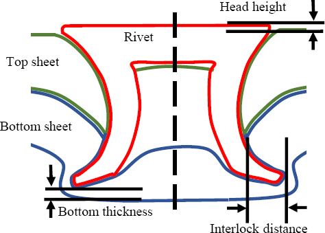
To produce strong and reliable SPR joints, manufacturers have defined three main aspects of joint quality: the interlock distance, rivet head height, and remaining bottom material thickness (Fig. 2). The interlock distance represents the radial distance between the outer surface of the rivet tail tip and the lower surface of the top sheet. The rivet head height is the height difference along the axial direction between the upper surface of the top sheet and the surface of the rivet head, and the remaining bottom material thickness is the minimum axial distance between the rivet tail tip and the lower surface of the bottom sheet24). In this study, the same bottom material (Al5052 sheet) was applied to all specimens to evaluate the joint formation behavior with various top sheet materials. Liu et al.25) stated that the quality guideline of SPR joints should comprise a minimum interlock distance of 0.4 mm for joints with an aluminum bottom sheet and 0.2 mm for joints with a steel bottom sheet, a rivet head height between -0.5 and 0.3 mm, and a remaining bottom material thickness of minimum 0.2 mm. However, Han and Chrysanthou26) mentioned that the head height should be as near to zero as possible to enhance the joint characteristics. Yang et al.27) described that the larger the interlock distance, the stronger the mechanical interlocking could be between the rivet and the sheet material.
The joint quality parameters (head height, interlock distance and remaining bottom material thickness) of the steel/Al, CFRP/Al, and Al/Al specimens are summarized in Table 3. All of the specimens satisfied the requirements for a head height of near to zero and a minimum bottom material thickness of 0.2 mm. However, among the various top sheet materials, larger interlock distances were formed in the order of steel, aluminum, and CFRP. The steel/Al joints achieved 39% larger interlock distance compared to the CFRP/Al. The steel/Al joints also demonstrated larger interlock distances compared to those of the Al/Al joints. In contrast, the CFRP/Al joints exhibited smaller interlock distances than the Al/Al joints. The various top sheet materials and rivet setting forces influenced the joint formation mechanism and subsequently resulted in variations in the interlock distances among the steel/Al, CFRP/Al, and Al/Al joints.
Table┬Ā3
Joint quality (head height, interlock distance and remaining bottom material thickness) of steel/Al, CFRP/Al and Al/Al joints
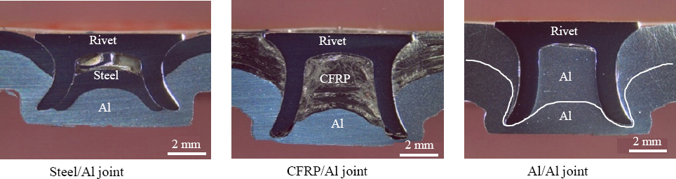
The joint cross-sections of steel/Al, CFRP/Al, and Al/Al joints are presented in Fig. 3. Generally, a higher rivet setting force is required for high-strength sheet materials because the resistance to piercing and flaring into the sheet material that the rivet encounters is determined by the material strength21). Usually, the rivet pierces the top material without much flaring. However, Abe et al.28) described that the rivet could partially flare during the piercing stage for high-strength top materials. In present study, the use of high-strength steel as the top sheet facilitated partial flaring during piercing of the top sheet in the steel/Al joints, and this earlier rivet flaring subsequently produced larger interlock distances. Moreover, a higher rivet setting force can contribute to a larger interlock distance, as stated by Li et al.29). This occur because the higher rivet setting force induces a larger deformation of the rivet tail into the bottom sheet material. In our study, comparatively higher rivet setting forces of the steel/Al joints could facilitate a larger deformation of the rivet tail during flaring of the rivet into the bottom aluminum sheet. However, when Al5052 is used as the top sheet in Al/Al joints, a higher rivet setting force is not a convenient option to create a larger interlock distance because of the comparatively lower strength of aluminum alloys. Instead, a smaller depth of the die cavity was used with a lower rivet setting force to induce early flaring of the rivet, thereby producing a larger interlock distance. This is possible because the die with a shallow cavity has higher constraint on the bottom material and can induce early flaring. However, despite the smaller depth of the die cavity, the joints with Al5052 as the top sheet experienced comparatively less flaring and more penetration during piercing of the top sheet than the steel/Al joints, and the Al/Al joints thus subsequently exhibited smaller interlock distances. Furthermore, the lower rivet setting forces of the Al/Al joints led to smaller interlock distances because of the lower deformation of the rivet tail.
Although the top sheet material strength and riveting forces were higher for the CFRP/Al joints, contradictory behavior was observed because of the SPR process-induced damage in the top CFRP. The CFRP/ Al joints showed smaller interlock distances than the steel/Al and Al/Al joints despite the fact that the maximum rivet setting force was required to pierce the rivet through the CFRP fibers. Unlike steel and aluminum, CFRP exhibits insignificant plastic behavior. The punching of the rivets thus caused matrix and fiber damage, fiber delamination, and cracking in the CFRP. Fig. 4 shows the CFRP fiber delamination and breakage around the rivet head in the cross-section of the CFRP/Al joint. Wang et al.30) also observed a similar type of fiber damage around the rivet head. Galińska and Galiński31) described that the rivet cut the fibers during the piercing stage, which resulted in disruption of the load trajectories through the subsequent plies, thereby reducing the thickness and resulting stiffness of the intact plies. Wisnom32) reported that the delamination and breakage of the fiber and matrix occurred because the fiber lying in the plane of the laminate did not provide reinforcement through the thickness; therefore, the composite relied on the comparatively weak and brittle matrix to endure loads in the rivet piercing direction. Consequently, the joints with CFRP as the top sheet experienced insignificant flaring and greater penetration during the piercing of the top sheet and thus subsequently exhibited smaller interlock distances compared to the steel/Al and Al/Al joints. In addition, higher rivet setting forces were required for the CFRP/Al joints, which resulted in the rivet partially piercing the bottom sheet before flaring and producing a smaller interlock distance because of the lower radial deformation of the rivet tail. Even though the top CFRP sheet of the CFRP/Al joint was 0.8 mm thicker than the top 590DP steel sheet of the steel/Al joint, the damage to the CFRP sheet and comparatively higher setting forces during the riveting process enabled easier penetration of the rivets without much flaring, thereby producing a smaller interlock in the bottom sheet.
Fig.┬Ā4
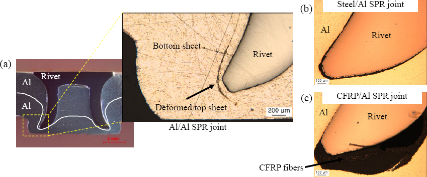
(a) CFRP fiber delamination and breakage around the rivet head during the rivet setting process, and insignificant top sheet degradation in (b) steel/Al and (c) Al/Al joints

The SPR process-induced top sheet degradation was less severe for steel and aluminum top materials than for CFRP. The punch energy of the rivet setting process could be absorbed by the plastic deformation of the top sheet material for steel/Al and Al/Al joints. As a result, the steel and aluminum top sheets exhibited insignificant degradation around the rivet head. Further investigation revealed that because of the comparatively higher formability of aluminum alloys, the rivet tail drew the top Al5052 sheet during the piercing stage, and the top sheet material remained around the rivet tail into the bottom sheet of the joint. Fig. 5 shows the crossection of the Al/Al joint containing deformed top sheet material around the rivet tail. Unlike the Al/Al joints, no significant drawing of the top sheet was observed at the rivet/bottom sheet interface for the steel/Al. However, delaminated CFRP fibers were evident below the rivet tail, which was driven in by the rivet tail during the riveting process.
Fig.┬Ā5
(a) Deformed top sheet material around the rivet tail for the Al/Al joint, and insignificant top sheet drawing phenomena by the rivet tail for the (b) steel/Al and (c) CFRP/Al joints
The force-displacement curve of a riveting process can be used as a fingerprint of the joint formation characteristic and resulting joint quality. The joint cross sectionsŌĆÖ analysis and force-displacement curve using interrupted test of the joining process can be related to the joint formation and its internal characteristics33). However, the simulations are able to expose the rivet penetration and flaring mechanisms, which can eliminate the requirement for the interrupted test of the joining process. Simulations were performed to investigate the riveting process of SPR joints with various top sheet materials. The force-displacement characteristic curves in both experiments and simulations were examined in this study to evaluate the joint formation and subsequent joint quality. The force-displacement curve can be divided into four major segments. Step I, sheets bend; step II, rivet pierces the top sheet; step III, rivet penetrates the bottom sheet; and step IV, rivet flares. Fig. 6 shows the force-displacement curves of the riveting process for the steel/Al, CFRP/Al, and Al/Al joints. During step I, sheets bend and partially fill the die cavity. At the beginning of this step, the force increases and the sheets bend until the rivet starts piercing the top sheet. At the end of this step, the force slightly drops because of the fracture initiation in the top sheet material as the force reaches the ultimate strength of the material and piercing begins. In step II, the force gradually rises and the rivet pierces the top sheet. However, a little flaring of the rivet tail was observed for the high strength top sheet material (e.g. steel). On the other hand, no significant flaring of the rivet tail was identified for the CFRP and aluminum top sheets. These phenomena can be related to the process-induced CFRP sheet damage and comparatively lower strength of the aluminum top sheet. At the end of this step, the force slightly declines as the resistance force by top sheet reduces once the material is perforated. In step III, the force rapidly climbs up because of material flowing inside the die cavity and the rivet pierces the bottom sheet. At the end of this step, the die is filled with the material while the rivet is still pushed to downward due to the punch pressure. In step IV, the rivet starts flaring. The length of this step can be related to the degree of the mechanical interlocking. At the end of this step, the force and displacement reach their maximum values. The force-displacement curves for steel/Al, CFRP/Al, and Al/Al joints were compared in Fig. 6(a) to 6(c). However, the major segments of the force-displacement curves in simulation can be distinguished more clearly. In step I, II and III, the higher force was required in the order of steel, CFRP, and aluminum top sheet. The higher force was needed for the bending and piercing of the high strength steel compared to the CFRP and aluminum sheets. In step IV, however, the higher force was needed for the CFRP/Al joint compared to the steel/Al and Al/Al joints. For the steel/Al and Al/Al joints, the partial flaring of the rivet in step II and III reduces the requirement of higher force in this step because of the earlier deformation of rivet tail. However, the CFRP/Al joint needed higher force in this step to deform the rivet tail. The SPR process-induced top sheet degradation of CFRP did not encounter adequate resistance force, and, consequently, did not experience flaring of the rivet in step I, II, and III, which resulted in the requirement of higher force in step IV to flare and set the rivet. Therefore, the joints with CFRP as the top sheet exhibited insignificant flaring and greater penetration in step I, II and III, thus experienced smaller interlock distance compared to the steel/Al and Al/Al joints. The cross-sections of steel/Al, CFRP/Al, and Al/Al joints at the end of riveting process in simulations are shown in Fig. 6(c). Similar as experimental results, among the various top sheet materials, larger interlock distances were formed in the order of steel, aluminum, and CFRP. The various top sheet materials influenced the joint formation mechanism and subsequently resulted in variations in the interlock distances among the steel/Al, CFRP/Al, and Al/Al joints.

3.2 Mechanical behavior of SPR joints with various top sheet materials
The static strengths of the steel/Al, CFRP/Al, and Al/Al joints were evaluated under lap-shear and crosstension loading. Table 4 summarizes the lap-shear and cross-tension strength results for the steel/Al, CFRP/Al, and Al/Al joints. For all specimens, the lap-shear strengths were higher than the cross-tension strengths. In the lap-shear tests, the load was mainly endured by the rivet, but in the cross-tension tests, the load was sustained by shearing between either the rivet tail and the bottom sheet material or the rivet head and the top sheet material34). As a result, the peak loads were higher for the lap-shear loading than for the cross-tension loading because of the comparatively higher strength of the rivet material in the lap-shear test than the shear strength of the sheet materials in the cross-tension test. However, the CFRP/Al joints demonstrated lower lap-shear and cross-tension strengths than the steel/Al joints. The CFRP/Al joints had 48% and 41% lower lap-shear and cross-tension strengths, respectively, than those of the steel/Al joints.
Table┬Ā4
Lap-shear and cross-tension strengths of steel/Al, CFRP/Al, and Al/Al joints
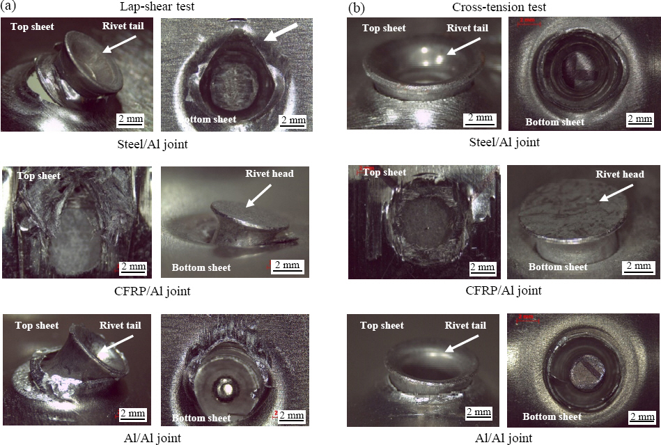
The failure mode of the SPR joint is a significant factor in the joint strength35). All of the lap-shear and cross-tension steel/Al specimens failed through the rivet tail pullout from the bottom sheet. In contrast, the CFRP/Al joints failed through the rivet head pullout from the top sheet. Fig. 7 presents the failure modes of the steel/Al, CFRP/Al, and Al/Al joints under lap-shear and cross-tension loading. The rivet tail pullout of the steel/Al joints indicates that the interlock between the rivet tail and bottom sheet mainly determined the lap-shear and cross-tension strengths, whereas the rivet head pullout of the CFRP/Al joints indicates that the joint strengths were limited by the locking between the rivet head and top sheet. The larger interlock distance in the steel/Al joints contributed to the higher lap-shear and cross-tension strengths. Moreover, the larger contact area between the rivet tail and bottom sheet resulting from the larger interlock distance also facilitated a higher frictional force and subsequently higher strengths of the steel/Al joints. Although the CFRP/Al joints had a smaller interlock distance, the rivet head pullout from the top sheet indicates that the degradation of the CFRP sheet due to fiber breakage and delamination dominated the failure mode and resulted in lower strengths. The lower fracture toughness of CFRP led to fiber breakage during the rivet setting process, and subsequently the damaged fiber around the rivet head further reduced the fracture toughness of the CFRP sheet during the strength tests. Kang et al.9) also observed a similar type of rivet head pullout for CFRP/Al joints because of the CFRP fiber breakage and matrix damage.
Fig.┬Ā7
Failure modes under the (a) lap-shear and (b) cross-tension tests of the steel/Al, CFRP/Al, and Al/Al joints
The difference in the lap-shear strengths between the steel/Al and CFRP/Al joints was more significant than that of the cross-tension strengths. During the lap-shear test, the stress concentration area of the rivet-head/ top-sheet interface was half the circumference of the rivet for the CFRP/Al joints, as shown in Fig. 8(a). The greater stress concentration on the damaged fiber around the half-circumference of the rivet head led to a higher degree of strength degradation of the CFRP sheet, resulting in a 48% lower lap-shear strength than that of the steel/Al joints. On the other hand, during the cross-tension tests, the load was distributed to the entire circumference of the rivet head, as shown in Fig. 8(b). Therefore, the cross-tension tests led to less degradation of the CFRP sheet around the rivet head, resulting in a 40% lower cross-tension strength than that of the steel/Al joints.
Fig.┬Ā8
Schematics of the load distribution in self-piercing riveting (SPR) joints under the (a) lap-shear and (b) cross-tension tests

The steel/Al joints demonstrated an 18% higher lap- shear strength and 24% higher cross-tension strength compared to the Al/Al joints. All of the lap-shear and cross-tension specimens of the steel/Al and Al/Al joints failed through the rivet tail pullout from the bottom sheet. This indicates that the interlock between the rivet tail and bottom sheet determined the lap-shear and cross-tension strengths of the steel/Al and Al/Al joints. Higher strengths of the steel/Al joints were observed because of the larger interlock distance and higher friction force at the rivet-tail/bottom-sheet interface resulting from the larger contact area created by the larger interlock distance. However, the difference in the cross- tension strengths was found to be more significant than that of the lap-shear strengths. During the cross-tension tests, the larger contact area of the rivet-tail/bottom- sheet interface compared to that in the lap-shear tests (approximately half the circumference of the rivet tail contributed to the friction force) enhanced the influence of friction, resulting in a greater difference in the cross-tension strengths (24%) than that in the lap-shear strengths (18%).
The CFRP/Al joints exhibited a 40% lower strength in the lap-shear tests and 27% lower strength in the cross-tension tests compared to the Al/Al joints. All of the lap-shear and cross-tension CFRP/Al joint specimens failed through the rivet head pullout from the top sheet. In contrast, the Al/Al joints failed through the rivet tail pullout from the bottom sheet. The failure mode of the CFRP/Al joints indicates that the strengths were mainly determined by the locking between the rivet head and top CFRP sheet, whereas the interlock between the rivet tail and the bottom sheet determined the strength of the Al/Al joints. However, the difference in the lap-shear strengths between the CFRP/Al and Al/Al joints was greater than the difference in the cross-tension strengths. The greater stress concentration on the damaged fibers around the half-circumference of the rivet head led to a higher degree of strength degradation of the CFRP sheet, resulting in a 40% lower lap-shear strength than that of the Al/Al joints. On the other hand, during the cross-tension tests, the load was distributed to the entire circumference of the rivet head, leading to less degradation of the CFRP sheet around the rivet head and resulted in a 27% lower cross-tension strength than that of the Al/Al joints.
In addition to the experiments, simulations were performed for the lap-shear test of SPR joints with various top sheet materials. Fig. 9 presents the joint strength and failure mode of steel/Al, CFRP/Al, and Al/Al joints in simulation. Similar as experimental observations, among the various top sheet materials, larger lap-shear strengths of the joints were found in the order of steel, aluminum, and CFRP. All of the lap-shear specimens failed through the rivet tail pullout from the bottom sheet. The failure modes of steel/Al and Al/Al joints are comparable with experimental observations. Unlike the experimental results, the CFRP/Al joints failed through rivet tail pullout from bottom sheet in simulation. This discrepancy occurred because the fiber breakage in the CFRP was comparatively less in simulation than the experimental observations. The limitations in simulation of CFRP materialŌĆÖs behavior was responsible for this disparity. Since the CFRP sheet was composed of seven unidirectional laminated layers with 0┬░ and 90┬░ orientations that experienced anisotropic characteristics and friction between the layers, these factors made CFRP behavior difficult to predict. As a result, the lap-shear joint strength of CFRP/Al was comparatively higher than that of the experimental observation.
Fig.┬Ā9
Failure modes under the lap-shear test in simulation for the (a) Steel/Al, (b) CFRP/Al and (c) Al/Al joints

More detailed effects of the top sheet materials on the lap-shear loads can be observed on the load-displacement behavior of the joints. The load-displacement curves of lap-shear tests showed a similar behavior between the experiment and simulation results as shown in Fig. 10. In initial stage, the load was mainly sustained by the bending of the top and bottom sheets36). Because of the dissimilar behavior of the top sheet bending, the load-displacement curves behaved in different manner. The CFRP yields comparatively earlier than the steel and aluminum top sheets. The CFRP sheet with damaged fiber failed through rivet head pullout from top sheet. This indicates that the interlock between the rivet head and top CFRP sheet determined the strengths of the CFRP/Al joints. On the other hand, the interlock between the rivet tail and bottom sheet determined the strengths of the steel/Al and Al/Al joints. Higher strengths of the steel/Al joints were observed because of the larger interlock distance and higher friction force at the rivet-tail/bottom-sheet interface resulting from the larger contact area created by the larger interlock distance.

4. Conclusions
This study examined the joint quality and static strengths of self-piercing riveted joints with various top sheet materials. For top sheet materials of steel, CFRP, and aluminum, large interlock distances of the joints occurred in the order of steel, aluminum, and CFRP. The analysis of jointsŌĆÖ cross-sections and the force-displacement curves generated in riveting process disclosed the variation in joint formation mechanisms for various top sheet materials. The CFRP sheet experienced less flaring but greater penetration in the early stages of riveting process because of the lower fracture toughness of the CFRP; as a result, the CFRP/Al joints had smaller interlock distances than the steel/Al and Al/Al joints. Higher joint strengths under lap-shear and cross-tension tests were observed in the order of steel, aluminum, and CFRP top sheets. The degradation of the CFRP sheet around the rivet head due to SPR process-induced fiber breakage resulted in failure through the rivet head pullout from the top sheet and lower strengths of the CFRP/Al joints. The CFRP sheet experienced a 48% lower lap-shear and 40% lower cross-tension strengths than that of the steel/Al joints. The steel/Al joints demonstrated an 18% higher lap-shear and 24% higher cross-tension strengths compared to the Al/Al joints.
 PDF Links
 PubReader
 ePub Link
 Full text via DOI
 Download Citation
 Print
Print


