Effect of Polarity and Oxide Fluxes on Weld-bead Geometry in Activated Tungsten Inert Gas (A-TIG) Welding
Article information

Abstract
In activated tungsten inert gas (A-TIG) welding, a thin layer of suitable activating flux is applied over the base metal to not only enhance penetration of the molten metal into root gap by 2 - 3 times compared to conventional TIG welding but also reduce the weld bead width considerably. This work focuses on examining the influence of TiO2, Fe2O3 and Cr2O3 activating fluxes (single component) on the weld bead geometry observed during the butt joining of 6 mm thick stainless steel (306 grade) plates by A-TIG welding under direct current straight polarity (DCSP). Three weld bead morphological parameters, namely, the depth of penetration, reinforcement and weld bead width, and their ratios are considered. The results are compared with those obtained during conventional TIG welding. The TiO2 and Fe2O3 fluxes exhibit the potential capabilities in enhancing penetration, reducing weld bead width, and reducing reinforcement. The Cr2O3 flux plays an insignificant role for redefining the weld bead shape, and in certain cases, this flux performs inferior compared to conventional TIG welding.
1. Introduction
Tungsten inert gas (TIG) welding is employed to obtaina defect-free reliable joint with appreciably good appearance, although it lacks productivity owing to low filler deposition rate and limited depth of penetration. So, proper edge preparation or multiple passes is often required. Correspondingly, heat input over a fixed area of the base plate increases leading to problems like broader heat affected zone (HAZ), undesired changes in microstructure and mechanical properties of the weldment, etc.1). These limitations paved the way for developing some improved TIG welding processes, like keyhole TIG (K-TIG), activated TIG (A-TIG), flux- bound TIG (FB-TIG), strengthening activated TIG (SA- TIG), advanced activated TIG (AA-TIG), laser-assisted TIG (LA-TIG), etc.2-6).
In A-TIG welding, a thin layer of suitable activating flux is applied over faying surfaces before arcing7). Fluxes for A-TIG welding include different oxides and halides8-10). Either a single component flux or a homogeneous blend of two or more such flux powders in appropriate proportion can be utilized11) after mixing with suitable solvents like acetone, methanol, or ethanol. Once the solvent dries out, welding can be carried out. A-TIG welding procedure is similar to that of TIG welding, except the additional step of application of activating flux on the base plates.
A-TIG welding was first reported in 196512). Later, Howse et al.13) used flux in TIG welding to overcome the problems associated with cast-to-cast variation in stainless steel. An attempt14) was madeto optimize welding parameters for an aspect ratio of 1.24. Effects of fluxes on surface appearance, weld morphology, angular distortion, etc. in autogenous TIG welding was explored by several researchers15,16). Shen et al.17) found that a growth in the percentage of TiO2 in a flux mixture can lead to better penetration with increased aspect ratio. Changes in surface tension gradient of liquid metal of the molten weld pool occur when activating flux is applied, that reverse Marangoni flow direction18) and thus, hot metal beneath the arc flows downwards leading to enhanced penetration. Effects of activating fluxes on weld-bead morphology were investigated by some researchers19-20) using AC polarity. In spite of several potential benefits of A-TIG welding, industries are still reluctant to extensively use this process mainly due to additional cost incurred by the flux itself and also due to the non-productive time for preparing and applying flux. Additionally, commercial fluxes tend to produce an inferior surface appearance15,16).
Although the feasibility and performance of A-TIG welding in joining various grades of stainless steel were studied by many researchers, only a few investigations emphasized on analyzing weld-bead geometry. Moreover, reinforcement is neglected by many researchers even though it is closely related to penetration and weld- bead width. An attempt is made in this work to explore capability of some fluxes in altering weld-bead geometryunder varying parameters. Objective of this experimental investigation is to examine the influence of TiO2, Fe2O3 and Cr2O3 single-component activating fluxes on weld-bead geometry during A-TIG welding of 6mm thick stainless steel plates at different levels of heat input, and to recommend the condition to obtain satisfactory weld-bead geometry.
2. Materials and method
306L stainless steel plates of 6mm thickness are chosen for butt welding maintaining a root gap of 2mm. Joining is carried out at the rectangular edge without any edge preparation. Filler material is used during welding. Composition of base material and filler is presented in Table 1.

Chemical composition of base material and filler
Three different fluxes, namely titanium oxide (TiO2), ferric oxide (Fe2O3) and chromic oxide (Cr2O3) are chosen for conducting A-TIG welding. Powdered flux is separately mixed with a solvent to make a semi-solid paste for applying on the base material. TIG welding (without any flux) is also performed for comparing with A-TIG welding results. As non-consumable electrode is employed in A-TIG welding, base plates can be quickly fused with DCEN polarity, thereby enhancing the rate of welding without overheating the electrode21). Hence, DCEN polarity is selected for this experimental work.
Some trial runs suggested that about 1.3-2.5kJ/mm heat input is desired22,23) to obtain satisfactory butt joint in TIG welding of the selected specimens. Low heat input cannot properly fuse the filler, while a high heat input undesirably increases distortion, HAZ and bead width. Accordingly, heat input is chosen within the afore-mentioned range. Current is varied from 90A to 130A with 10A increment, while welding speed is maintained constant. A detailed account of fixed and variable parameters used here is presented in Table 2 and Table 3, respectively.

Fixed parameters used in this investigation

Variable parameters used in this investigation
As-received samples are first cleaned using ethanol. Activating flux, which comes in powder form, is then mixed with acetone solvent to prepare a semi-solid paste. This paste is then applied manually on the faying surfaces and surrounding top surfaces of the base plates using a soft brush (Fig. 1a). The thickness of this flux layer is attempted to maintain constant for all the cases. Activated flux coated base plates are then carefully placed below the welding torch maintaining the pre-defined root gap and arc length. Supporting bare plates are also placed at both the ends of the root gap so that the arc can be constituted on the uncoated plate and can also be terminated on another uncoated plate. It ensures a uniformity in weld-bead deposited on the intended flux coated base plates. Moreover, constitution of the electric arc on a bare plate is easier as compared to the same for flux coated plate.

Typical appearance of flux coated plates prior to welding and the corresponding weld bead after A-TIG welding
Sufficient time is spent to allow drying ofthe flux layer (it typically takes 20-30s as acetone quickly evaporates). After setting up required parameterson the welding machine (KEMPPI Master Tig MLS 3003ACDC) and opening the shielding gas flow valve, the arc is established to carry out welding. Vehicle that holds the torch is also started to move at a pre-defined speed, and at the same time, filler is manually fedto the welding zone. By virtue of experience, filler feeding rate is attempted to keep constant. After natural air cooling of the welded plates, the jointed plates are sectioned cross- wise to expose the weld zone. The exposed surface is further finished by polishing through belt grinder and emery papers of various grades, and finally with buffing. Smooth exposed surface is finally etched by a suitable reagent to reveal a clear dichotomy between the base plate and the weld metal (Fig. 2). Several weld-bead parameters are then measured using a portable metallographic microscope.

Schematic representation of the cross-section of a typical butt-welded joint indicating relevant parameters
3. Results and discussion
Important observations made during A-TIG welding are the presence of spatter and slag. Although TIG welding is usually free from spatter, the application of activated flux gives rise to mild welding spatters. However, such spatter does not emerge in the form of molten metal droplet; instead, it comes in the form of hot oxide particle (oxide spatter). Spatter and slag formations were also observed by Patel et al. during A- TIG welding of stainless steel24). Spatter formation tendency was found to have proportional relationship with the arc constriction capability of the concerned activating flux. In terms of arc constriction capability, the three fluxes used in the current investigation can be ranked as: TiO2>Fe2O3> Cr2O3 (as discussed in following passages). Accordingly, the so-called “oxide spatter” is found prevalent particularly in the case of TiO2 flux,whereas Cr2O3 based A-TIG welding is found almost free from it. Irrespective of flux ingredient, spatter in A-TIG welding is meager if compared with the same observed in shielded metal arc welding. Moreover, oxide spatters do not make a solid bond with the base plate after deposition, and thus, can be removed easily by wire brushing.
Three fundamental weld-bead geometrical parameters (P, W and R) for TIG and A-TIG welding with varying levels of current are presented in Table 4. As shown in Fig. 2, the penetration (P) indicates the depth of the weld-bead below the original surface of the base plates. The reinforcement (R) indicates the height of weld-bead above the original surface of the base plates. The actual width of the weld-bead measured at the top surface of the base plates is termed as width (W). Two derived morphological parameters, namely, reinforcement form factor (RFF) and penetration shape factor (PSF) are also displayed in Table 4. RFF is the ratio between W and R, while PSF is the ratio between W and P. PSF basically gives inverse of aspect ratio; thus, lower PSF is better. Absence of few values of weld-bead parameters in A-TIG welding with minor heat input (or low current) indicates that joining does not take place at those conditions. Usage of oxides as activated flux during welding also gives rise to the formation of slag on the molten metal pool that creates a thin fragile layer over the weld-bead. However, this layer automatically tends to leave the weld-bead during cooling after forming crocodile cracks. It is also observed that the tendency of slag formation is lower for the case of Cr2O3 flux.

Weld-bead geometry of butt jointed plates with DCEN polarity
3.1 Heat input calculation
As given in Eq. (1), the heat input (HI) can be expressed in terms of set current (I), close circuit voltage (V), speed (S), and a thermal efficiency (η). The η for conventional TIG welding normally varies from 59.1% - 86.9%25). Thus, 80% efficiency is considered here for analysis. Since close circuit voltage recorded during welding differs independently from one experiment to another (primarily based on activation potential of workpiece surface required to dislodge electrons), so heat input also varies even if the current is the same. Flux layer can restrict the free flow of electrons from the base plates and thereby increases activation potential required to form and maintain the electric arc during welding. Since heat input is proportional to the arc voltage, so a larger heat input is expected for the cases of A-TIG welding as compared to TIG welding at the same current and speed. The same is also reflected in Table 4.
When compared with A-TIG welding, lesser heat input is desired for deposition of weld-bead in TIG (Table 4). In TIG welding with a heat input of 1.35kJ/mm, fusion of the base plate is found to occur; although, depth of penetration is found very small (indicates improper fusion, as discussed in successive sections). However, no fusion takes place with similar level of heat input in A-TIG welding. It can be possibly due to the restriction on heat flow imposed by the insulating flux layer present on the base plates. Accordingly, the arc heat fails to properly penetrate the base plates through the thermally non-conductive flux layer. Thus, base plates do not fuse even though the arc heat remains the same (or similar) for the same current. Requirement of heat input is particularly more in the case of Cr2O3 flux based welding. This can be attributed to the thermal and electrical non-conductive nature of Cr2O3 flux23). Both the fluxes TiO2 and Fe3O4 are semi-conductive in nature26,27), and consequently, lesser arc heat can fuse the base plates.
It is worth mentioning in this context that full penetration is also achieved with high level of heat input. For the cases of excess penetration (Fig. 3), depth of penetration is measured beyond the reverse surface of base plate. In such cases, penetration P = (t + e), where “t” is the actual base plate thickness (i.e., 6 mm) and “e” is the thickness of the weld metal penetrated below the reverse surface of the base plates. Consequently, penetration value higher than 6mm is recorded. However, this situation is found to occur in only one case in this investigation with TiO2 flux based A-TIG welding, where penetration of 6.71mm is observed at a heat input of 2.20kJ/mm. Typical appearance of the weld-bead with varying fluxes and heat inputs is shown in Fig. 4.
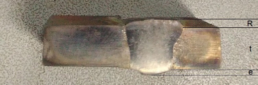
Cross-section of weld bead obtained by A-TIG welding with TiO2 flux with 2.20kJ/mm heat input indicating excess penetration (e), along withreinforcement (R) and plate thickness (t)

Typical appearance of the weld bead with 100A and 130A current for conventional TIG and A-TIG welding with TiO2, Fe2O3 and Cr2O3 fluxes
3.2 Impact of activating flux on penetration
Variation of the depth of penetration (P) with welding current for conventional TIG as well as for A-TIG welding with three fluxes is shown in Fig. 5. In general, penetration is found to increase with current (alternatively, heat input). This can be attributed to the fact that higher heat input resultsin sufficient melting of both the base plate and filler metal. Accordingly, fluidity and wettability of the molten metal pool improve, which facilitates quick flow of molten metal deeper into the root gap leading to increased penetration. The rate of increment in penetration with heat input, however, varies from one case to another. Conventional TIG welding is found to fetch 3.46mm penetration with 2.20kJ/mm heat input. This is also close to the maximum achievable penetration (typically 3.5mm) in TIG welding.
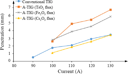
Plot of variation of penetration (P) with arc current
TiO2 and Fe2O3 flux based A-TIG welding processes exhibit much higher penetration as compared to TIG welding. At lower heat input, both the fluxes show a similar level of penetration; however, TiO2 flux clearly produces more penetration compared to the other one at higher levels of heat input. In fact, full penetration of 6mm is achieved with TiO2 flux at 2.20kJ/mm heat input. The tendency of producing deeper penetration in A-TIG welding can be attributed to the well-accepted phenomenon, called Reverse Marangoni Effect13). In normal scenario, such as in atmosphere or oceanic currents, hot fluid tends to flow upward pushing back the cold fluid down. In the weld-pool for conventional TIG welding, the hot molten metal remains at the top surface layer. However, usage of suitable activating flux can reverse the convection flow within the molten weld metal pool owing to the changes in surface tension induced by the active layer of molten flux5). Here, hotter metal beneath the arc flows downward through the narrow root gap between two plates. This enhances melting of base metals deep inside the root gap, and therefore, higher penetration is achieved.
However, Cr2O3 flux is not effective for enhancing penetration as 3.43mm maximum penetration is recorded at a very high heat input (2.43kJ/mm). It is similar to that obtained in conventional TIG welding at the same level of heat input. Incapability of Cr2O3 flux towards enhancing penetration can be attributed to the non-conductive nature of Cr2O3, which causes dispersion of the flux from base plates when the arc tends to move over it. Thus, it plays no role in reversing Marangoni Effect; instead, it leaves the welding zone without any contribution (thus no slag layer is observed over the weld-bead for this case, as mentioned earlier). Accordingly, no noticeable enhancement in penetration as compared to TIG welding is recorded for Cr2O3 flux based A-TIG welding.
3.3 Impact of activating flux on weld-bead width and reinforcement
Variation of weld-bead width (W) with current is shown in Fig. 6. In general, width of the weld-bead is found to increase with heat input. Higher heat input tends to melt down a wider area of the base plate surrounding the root gap (as welding speed is maintained constant). This, along with improved fluidity and wettability of molten metal pool, leads to increased weld-bead width. Conventional TIG welding shows comparatively narrower weld-bead as compared to A-TIG welding with all the three fluxes. However, this deviation reduces with increase in heat input, especially for TiO2 and Fe2O3 fluxes. In fact, almost same bead width is noted at 2.20kJ/mm for TiO2 flux based A-TIG welding (7.14mm) and for conventional TIG welding (7.11mm). Usage of an appropriate activated flux leads to constricted arc, and thereby increases heat density. However, at lower levels of heat input, deeper layers of material of the base plates fail to fuse (as evident by lower penetration). Due to constant filler deposition rate, weld-bead tends to spread through a wider region instead of penetrating deep into the root gap. Accordingly, a wider weld- bead is observed even though the arc is constricted. However, with an increase in heat input, deeper layers of the base metal melt down properly, and consequently, filler metal penetrates the root gap (instead of spreading over wider area). This beneficial effect of arc constriction phenomenon can be observed at higher levels of heat input.
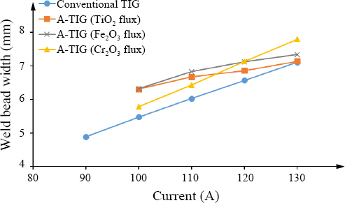
Plot of variation of weld bead width (W) with arc current
Cr2O3 flux shows a trend of increasing bead width that is quite similar to that observed in conventional TIG welding. This can be possibly due to automatic dispersion of the Cr2O3 flux during welding, as mentioned earlier. This flux does not contribute to modifying the arc or altering the molten metal flow direction; instead, it increases welding voltage (by restricting the free flow of electrons prior to dispersion from the surface), and thereby increases heat input. 2.20kJ/mm heat input is obtained with 130A current for conventional TIG welding, while Cr2O3 flux based A-TIG welding showed 2.43kJ/mm at the same current. Accordingly, the weld- bead is also found wider in Cr2O3 flux based A-TIG welding as compared to TIG welding for the same current. However, a comparison with respect to heat input can eliminate such deviation. For example, 7.11mm bead width is observed in conventional TIG welding for 2.20kJ/mm heat input, while a similar bead width of 7.13mm is observed for similar level of heat input (2.12kJ/mm, 120A) in Cr2O3 flux based A-TIG welding.
Reinforcement (R) primarily relies on the volume of the filler material deposited per unit length and corresponding root gap, penetration and weld-bead spreading. In the present investigation, neither the root gap nor the filler metal deposition rate is varied. Thus, with an increase in penetration and/or increase in weld-bead width, reinforcement is expected to decrease. This trend is also reflected inthe reinforcement-current curve (Fig. 7).

Plot of variation of reinforcement (R) with arc current
At lower ranges of heat input, reinforcement is found larger as a result of shallow penetration. Reinforcement is also found to with current due to the consequent increase in penetration; however, the rate of reduction varies for different cases. Particularly, TiO2 and Fe2O3 fluxes show potential capability in reducing reinforcement to a greater extent at higher ranges of heat input. In these two cases, significant increase in penetration leads to a steep reduction of reinforcement, even though a narrower weld-bead is recorded. In other cases, limited penetration results in comparatively higher reinforcement, even at higher ranges of heat input. It is worth mentioning in this context that reinforcement can be effectively reduced either by increasing welding speed or by reducing filler deposition rate. Higher welding speed, however, can lead to insufficient fusion and incomplete penetration due to lack of heat input per unit length. The ultimate results will be defective welding and high rejection rate. Reduction in filler deposition rate is one safe way to keep reinforcement minimum.
3.4 Impact of activating flux on RFF and PSF
Since RFF is the ratio between weld-bead width (W) and reinforcement (R), so spreading of the weld-bead and/or reduction in reinforcement can increase the RFF. However, both W and R are related to penetration as filler metal is deposited at a constant rate throughout the work. In general, an ascending trend for RFF with heat input can be observed in Fig. 8. Both TIG and Cr2O3 based A-TIG welding processes show ascending RFF with heat input. The rate of such ascend is almost same within the range of heat input studied in this work. This can be due to a similar rate of increment in weld-bead width and consequent reduction in reinforcement with heat input for both the cases.
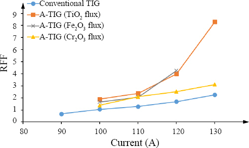
Plot of variation of reinforcement form factor (RFF) with arc current
At lower ranges of heat input, TiO2 and Fe2O3 based A-TIG welding processes also show low RFF, which is comparable with that observed in TIG and Cr2O3 based A-TIG. However, as heat input increases, penetration also increases steeply, and at the same time reinforcement reduces. Moreover, the rate of increase in weld- bead width drops at higher heat input due to palpable influence of constricted arc. As a combined result, a steep increase in RFF is observed at a higher range of heat input in TiO2 and Fe2O3 flux based A-TIG welding. It is to be noted that the reinforcement becomes zero at 130A current with Fe2O3 flux based A-TIG welding, and thus RFF becomes theoretically infinite. So, this data is neglected while plotting RFF with current (Fig. 8).
Penetration shape factor (PSF), the ratio between weld- bead width (W) and penetration (P), basically gives the inverse of the aspect ratio of the weld-bead. Usually, deeper penetration with narrow weld-bead is desired in butt joining of plates, and therefore, the smaller is the PSF, the better is the welding. Plot of PSF with arc current (Fig. 9) displays a descending trend for PSF with heat input for all the cases. Such a decreasing trend indicates that the rate of increase of penetration with heat input is much higher than the consequent rate of increase of weld-bead width. Lack of penetration with Cr2O3 based A-TIG welding leads tohigher PSF. Similar results can also be observed for TIG welding because of limited penetration. On the other hand, significantly high penetration along with constricted arc (narrow weld-bead) leads to lower PSF for other two cases.

Plot of variation of penetration shape factor (PSF) with arc current
4. Conclusions
In this article, 306L stainless steel plates of 6mm thickness are butt joined using similar grades of filler metal by conventional TIG welding and A-TIG welding individually with TiO2, Fe2O3 and Cr2O3 single component activating flux with DCEN polarity. Based on the observations and results obtained, the following conclusions can be made.
1) Slag formation takes place in the form of a thin fragile layer over the weld-bead due to the application of oxide-based activated flux. Cr2O3 flux shows low tendency to produce slag.
2) Cr2O3 flux plays no role in improving penetration or shortening weld-bead width as it automatically detaches the base plate surface as the arc approaches, and subsequently moves away from weld zone without altering arc characteristics and molten metal flow. Instead, it widens weld-bead by unnecessarily increasing heat input as compared to conventional TIG welding.
3) TiO2 and Fe2O3 fluxes show potential capability in enhancing penetration, shortening weld-bead width and reducing reinforcement by reversing Marangoni effect and constricting arc. In fact, full penetration of 6mm is achieved with TiO2 flux at 130A current at 2.20kJ/mm heat input.
4) TiO2 and Fe2O3 fluxes are also capable in reducing penetration shape factor (PFF) (or improving aspect ratio); however, TiO2 is found more effective as compared to Fe2O3 flux.
This work is carried out using three single-component activating fluxes, which are based on oxides of metals. There exist several other flux components including oxides and halides that may exhibit considerably different weld-bead geometry. Moreover, a mixture of several flux components in appropriate proportions may provide better results, as studied by Tseng et al.11). Furthermore, the entire work of this investigation is carried out on 6mm thick stainless steel plates. In one case with higher ranges of heat input in A-TIG welding, complete penetration of 6mm is recorded. Accordingly, further research works may be undertaken to reveal the extent of the capability of various single, binary or multi-component activating fluxes in enhancing the weld- bead morphology during A-TIG welding of thicker samples.