Welding of Thin Tab and Battery Case for Lithium-ion Battery Cylindrical Cell Using Nanosecond Pulsed Fiber Laser
Article information

Abstract
In battery packing, the battery case and tab should be joined; fabricating this joint has been a challenging issue owing to dissimilar base materials and different thicknesses. A battery case is generally made of steel as it demonstrates high strength and hardness as well as excellent corrosion resistance; an aluminum tab has significant ductility and thermal expansion, thereby making it challenging to weld the joint. Laser welding is a non-contact technology providing rapid cooling. Therefore, it has been applied for the welding of several dissimilar metals joints. Joints welded through this technology result in a reduction of the brittle intermetallic phase and lower electrical resistance compared with other technologies. In this paper, the battery case and thin tab were welded via pulse laser irradiation. The experiment was performed with the laser power ranging from 10 to 20 W, and the remaining parameters were constant. The welding results were analyzed in terms of macrostructure and mechanical performance. Images from the scanning electron microscope showed that the laser power significantly influences the welding joints. Chemical composition analysis of the cross section presented two significant diffused material parts in the fusion zone. Hardness, which characterizes the mechanical properties of the joints, exhibited significant differences between the base material and fusion zone as well as the two diffused parts in the fusion zone.
1. Introduction
In energy storage technology, the demand for lithium- ion batteries is rapidly rising in the electronic market as well as its application in various areas, especially in the automobile industry1-3). Cylindrical cells attribute with low expenses for production and easy to fabricate, therefore, the design has been widely applied in many different electrical devices. In addition, cylindrical cells were able to minimize the deformation of the case. The case can protect the electrodes and electrolyte when it is subjected to certain abnormal conditions4). Several battery cells are joined to form a module, modules then are connected in order to increase battery capacity so that it can be applied as an automotive battery. Therefore, significant joining must be performed, typically tabs are consumed to connect cells together in order to transfer electricity between cells5,6). During packing battery cells, tab and battery case must be joined. The tab is usually made of aluminum and copper. Steel is generally used as battery cases. However, this dissimilar joining is a really challenging issue due to the different physical and chemical characteristics of the materials. Several studies have been investigated these dissimilar joints in terms of battery application. Zhang et al.7) and his colleagues demonstrated the joining of pure aluminum sheet and low carbon steel sheet using friction stir brazing technology, Zn was used as filler material in the joint. The result showed that two distinct intermetallic compounds layers were found with a certain experimental condition while the total thickness of the layers was less than 10 . A joining of 6-mm thickness Al 6061 to AISI 1018 steel was performed by Chen et al.8) using a method of combining the effects of fusion and solid-state welding. The formation of holes and pores exposed on top of the weld was detected in the joint. Hwang et al.9) has been investigated the effect of Mg in Al-Mg alloy on the joint strength and microstructure of the Al-Mg and steel joint. This joint was performed by the spot resistance welding. The effect of pure aluminum inserts which were put into the interface of the joint was investigated in the paper. The result showed that the cross-tensile strength of steel and pure aluminum was remarkably higher than that of steel and Al-Mg alloy joint. In addition, fracture occurred in the aluminum side when the joint was inserted with pure aluminum. Laser welding has been considered to apply for various fabrication10-29). The technique is a non-contact joining technology that resulted in lower electrical resistance in comparison with other welding methods such as spot welding and ultrasonic welding30). Moreover, the effort of reducing the manufacturing cost in battery production has been studied with many investigations of the materials. Therefore, this study aims to investigate the effect of low-cost laser technology on welding the dissimilar materials of battery case and tab for lithiumion batteries. In the present experiment, the nanosecond fiber laser source is applied to join the thin aluminum alloy tab and nickel-plated steel battery case, the result then is analyzed in macrostructure and mechanical properties.
2. Materials
In this study, the battery case was made of electrical nickel-plated steel (composing of 0.03% C, 0.003% Si, 0.23% Mn, 0.011% P, 0.008% S) and a thin tab comprised of pure aluminum as the base material. Thin tab with a thickness of 0.087 mm and 7 mm in width was selected. The thin tab is cut 10 mm in length as the specimen for the experiment. A commercial cylindrical battery cell with a height of 73.5 mm was used. The bottom thickness of the battery case was 0.3 mm. Moreover, a 10 thin Nickel layer was coated on the battery case.
3. Experiment
The experimental setup of this study is shown in Fig. 1. Ytterbium Pulsed fiber laser (IPG-YLPM, IPG photonics, Southbridge, USA) with maximum laser power of 20 W was employed as the laser source for experiments. Laser beam features with a wavelength of 1064 nm, laser pulse duration of 200 ns, a spot size of 30. The laser beam was transported to lens with a focal length of 190 mm. In this experiment, welding results were obtained with the laser powers in a range from 10 to 20 W. A thin aluminum tab was placed on the Nickel coated surface of the battery case.
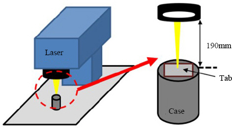
Experiment setup
The welding process was performed following a welding path which is described in Fig. 2, without shielding gas. The welding path was a combination of two shape parts: 1) circular and 2) zigzag shape with a consistent welding speed of 1 mm/s. The welding path started from a circular line as a boundary. When the circle closed, the welding path continuously went inside that circle and followed parallel zigzag lines with a distance of 0.1 mm between each two-line. These zigzag lines ended and reversed direction when it met the outer circular line.
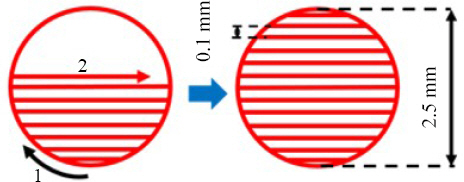
Schematic of laser welding path
4. Result and Discussion
4.1 Weld surface appearance
Scanning Electron Microscope (SEM) is firstly employed in order to observe the macrostructure of the top surface of the welding zone. Fig. 3 shows the SEM images of the weld surface in the laser power from 10 W to 20 W. The surface morphology is well recognized in this observation with weld metal and spatters. In the closer look, Fig. 4 indicates a top view image of the joint in the laser power of 10 W within the zigzag welding zone. The melt exists along each processed zigzag line. From the top view, the formation of voids in the middle of the welding path can be recognized, the formation is due to the solidification process. Moreover, most spatters attaches on the surface with a diameter smaller than 10 are also detected around the laser processed lines, these spatters are ejected from welding pools as the explanation of the swelling phenomenon according to Gao et al.31) Surface tension and the melt flow in the melt pool significantly influence the formation of the spatters. the molten flow in the molten pool is accelerated mainly by the metallic vapor from the keyhole. When the flow of the molten material in the molten pool can overcome the surface tension, spatters are formed and ejected into the air then drop back on the surface due to gravity. As a result, the more unstable of the molten pool, the more spatters are produced.

SEM images of the top surface of the welds

SEM image in the top view of the joint with laser power of 10 W
In addition, the changes in top surface appearance in different laser powers are shown in Fig. 5. In higher laser powers, 15 W and 20 W, visual observation reveals an increase in molten materials existed on top surfaces. The melt overflows and solidifies around the processed lines. Molten metals solidify with overlaps following welding direction. The apparent width of the zigzag lines increases with increasing laser powers while the laser spot size is 30. Besides, the number of voids formed in the middle of the lines starts to reduce when the higher laser powers are used. Few voids can be recognized when the joint is processed with laser power of 15W. However, In the joint with laser power of 20 W, the surface is covered with molten materials and voids on the surface are hard to be detected. It is clear that higher laser power has significantly contributed to the formation of molten materials as well as the spatters on the surface. It is evident that the power has influenced the amount of the base material which is melted. When more power energy has used an increase of the base materials are melted. In addition, the recoil force which is generated due to metal evaporation in the keyhole is produced more in the higher laser. This high recoil pressure also accelerates the flow inside the molten pool and tend to push the melt flow upwards. As a result, the weld metal is formed more on the surface and more spatters are produced. It is interesting to note that there should be the displacement or disappearance of the voids on the surface. However, with a clue of an increase of the molten materials on the surface, the assumption of the displacement of the surface voids should be reliable.
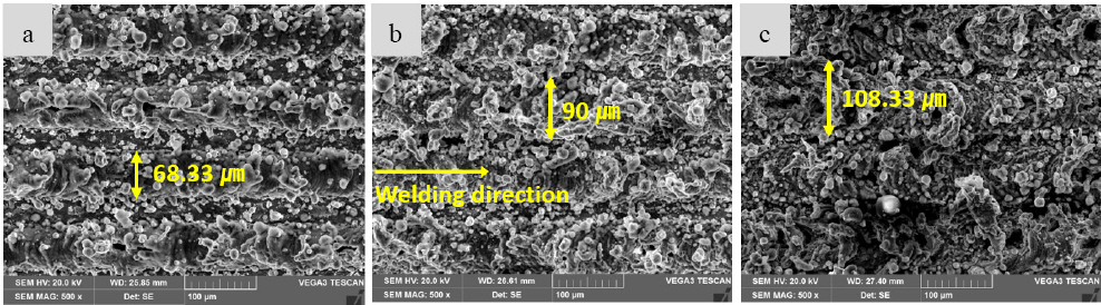
SEM images in top view of (a) 10 W; (b) 15 W and (c) 20 W laser power
4.2 EDX analysis
The chemical composition in the fusion zone is analyzed with Electron Dispersed X-ray (EDX), the analysis shown in Fig. 6 indicates two separating intermixture zones in cross-section of 10 W laser power. The major chemical components of the upper part of the fusion zone are Al and the lower part comprises mainly Fe. A spot 1 demonstrates chemical composition with 85.14% Al, 3.2% Fe, and 10.73% C. It is evident that a large amount of Al has been melted and solidified at the region with a little access of Fe, namely rich-Al zone. The small amount of Fe which appears in the zone is produced by the diffusion of the melted iron after being pushed upwards. A spot 2 contains a large amount of Fe with the weight percentage of 52.1%, then a rich-Fe zone tends to be formed. However, the diffused Al exists in the zone is noteworthy with the weight percentage of 19.94%. Nickel coated on the interface of the lower layer is diffused by laser irradiation and mixes in the fusion zone. This type of fusion zone formation is due to dissimilar chemical and mechanical properties. These mismatched characteristics make the metals have low solubility during the solid solution. The difference in physical properties such as melting temperature and thermal expansion causes the formation of the fusion zone with uncompleted solubilization.
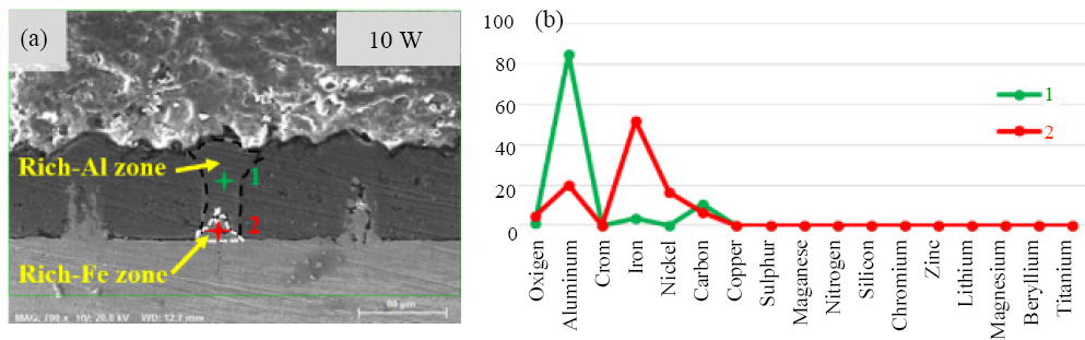
EDX analysis within fusion zone in upper layer (a) fusion zone, (b) EDX analysis result
4.3 Hardness test
The laser welding process characterizes the high cooling rate or rapid solidification process of the melt, which results in a high hardness on interacted materials32). In order to clarify the comparison on hardness between solidified materials and the base materials, the hardness test is performed horizontally around the fusion zone in upper layer material. The result shows in Fig. 7 and reveals that low harnesses are recorded outside of the fusion zone which comprises the base material. The values start increasing and reach a peak of hardness as the distance comes to the center of the fusion zone. As the distance goes far away from the center of the fusion zone, the test reports a reduction in hardness values. At 40 from the center of the fusion zone, the weld material in joint with 20 W laser power is much harder than the others. The assumption of the great increase of hardness at the center of the fusion zone is comprehensible. The fusion zone of the mentioned joint comprises of the large width of solidified materials that contribute high hardness in comparison with base materials. Moreover, in the middle of the fusion zone, a large amount of the solidified Fe is detected, which is expected to cause high hardness. As mentioned above, a rich-Al fusion zone surrounds the solidified Fe, this reports to a decrease of the hardness. In addition, aluminum base material owns low hardness which causes a significant increase in hardness when the distance is far from the center of the fusion zone. The high hardness is considered as the cause of cracks forming in the welds.
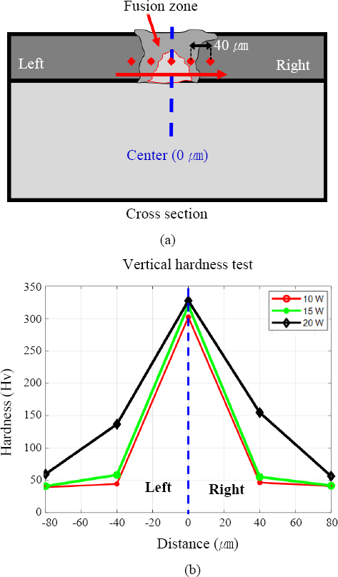
Hardness test on the horizontal direction in the fusion zone (a) Illustration of the test, (b) Hardness result
5. Conclusion
In the present experiment, the attempt of welding a thin aluminum tab and nickel-plated steel is performed using a cost-effective nanosecond fiber laser, the effect of laser powers on the joints is analyzed with macro- structure and mechanical properties. The key observations of this study can be summarized as follows:
1) It is possible to weld the different thicknesses and materials of the battery case and tab with the nanosecond pulsed fiber laser.
2) The laser power has a significant impact on the formation of weld metal and spatters on the weld surface. When higher laser power is used, more molten materials are produced and cover the surface voids.
3) The fusion zone through the analysis of a cross-section of the joints revealed two separate intermixture solidified materials, including Al-rich and Fe-rich zone. As a result, a rapid increase of the hardness at the center of the fusion zone is reported.
4) Fusion zone, especially the Fe-rich zone is obtained with the highest hardness and the hardness increases with increasing laser powers.
5) Future studies would focus on the dislocation of voids formation depends on laser powers. Moreover, intermetallic compounds and the intensive fusion zone analysis will be taken into account.
Acknowledgement
The research described herein was sponsored by the National Research Foundation of Korea (NRF) grant funded by the Korean government (MSIP; Ministry of Science, ICT & Future Planning) (No. 2019R1A2C- 1089644). The opinions expressed in this paper are those of the authors and do not necessarily reflect the views of the sponsors.