Anticorrosion Performance of FCAW Cladding with Regard to the Influence of Heat Input
Article information

Abstract
Heat input plays a significant role in flux cored arc welding (FCAW) for producing quality welding. Weld cladding improves corrosion resistance and other mechanical properties. Selection of appropriate heat input is required to get optimum quality of the cladding. In this experiment, FCAW cladding of duplex stainless steel is done on low alloy steel under CO2 gas shield. Three sets of heat input are chosen for experimentation in which each level of heat input comprised of three sets of current and voltage in such a way that the heat input level remained nearly constant. The output parameters like corrosion rate is measured and microstructures are evaluated. The relationship between heat input and corrosion rate is evaluated by means of polynomial regression analysis and the results matched with proposed model with small variations. The results showed that corrosion rate increases with increase in heat input within the experimental domain. Minimum corrosion rate is obtained in the present investigation at 0.49 kJ/mm heat input with 170A weld current, 27V weld voltage and 7.5 mm/s weld torch travel speed. For a particular heat input, corrosion rate is found to vary with different weld current. Microstructure of duplex stainless steel cladding shows presence of austenite phase, and ferrite phase. For an increase in heat input, the microstructure of clad part sacrifices more amount of ferrite phase that exhibits more amount of corrosion.
1. Introduction
Materials which possess better surface dependent properties like corrosion, erosion and fatigue resistance can be used to cover other low grade base materials to improve their service life. These materials are costly as compared to the base materials, but prove themselves to be economical due to longer life.
Different types of surfacing techniques such as coating, plating, buttering, cladding, metal spraying, etc. can be used to deposit materials. Cladding is a more common surfacing technique that involves weld deposition of materials of several millimeters in thicknesses on a corrosion-prone material for protection from corrosion or for improving surface strength and thus increasing service life of the parent material with very little change in the microstructure1). Weld cladding creates a new surface layer with different chemical composition than the base material which, in general, is harder than the cheaper base material. Compared to other techniques, weld cladding has some distinct advantages as it can provide high hardness, corrosion and erosion resistance in conjunction with good bonding and favorable microstructures.
In recent years, weld cladding processes have become popular in numerous industries such as chemical and fertilizer plants, aviation, mining, agriculture, power generation, food processing and photochemical industries as a cost effective engineering solution of protecting low carbon and low alloy steels against corrosion attack by providing a protective surface layer2).
Among the welding processes employed for cladding, gas metal arc welding (GMAW) is widely accepted by the industry due to some advantages like high reliability, all position capability, ease of use, low cost, high productivity, suitability for both ferrous and nonferrous metals and alloys, high deposition rate, absence of flux, cleanliness and ease of mechanization. Performance of GMAW cladding can be enhanced by applying properly selected process parameters at appropriate levels. GMAW can be used for good quality cladding having favourable microstructure which may have adequate corrosion resistance property3). Shihab applied multiple objective optimization based on ratio analysis (MOORA) technique in a recent work for evaluating proper parameters that could affect time and power required for GMAW cladding. They observed welding current and welding voltage to be responsible for reducing time and power required for GMAW cladding4). Spatter is one common welding defect that is generated during GMAW. In a recent work, Kang et al. showed spatter can be minimized by utilizing proper inter-wire distance and range of current for leading and lagging electrode5). Flux cored arc welding is a special type gas metal arc welding process in which annular consumable electrode is filled by flux. This additional flux protects further the weldment.
The mechanical strength of the clad metal formed by FCAW is influenced not only by the composition of the metal, but also by the clad bead shape and its geometry. In modern industries, large quantity of welded part having acceptable quality can only be achieved by proper selection of process parameters and mathematical model6). The acceptable clad bead geometry depends on arc voltage, welding current, gas flow rate, wire feed rate, welding speed, torch angle, tip-to-nozzle distance, etc.7). The relationships between input process parameters and bead parameters were investigated with the help of various mathematical models8,9). Penetration of clad materials causes dilution which involves loss of costly alloys from the clad materials migrating to the base metal. High dilution causes loss of performance of clad materials in most of the cases. So heat input along with different process parameters are to be set at optimal values to effect minimum dilution10).
Heat input plays an important role in producing quality cladding. It directly influences the weld bead parameters, mechanical properties and corrosion resistance properties11). Frei et al. observed refined heat effected zone in cold metal transfer at low heat input gas metal arc welding that reduced many unwanted phenomena which could be seen in traditional heat affected zone in case of GTAW welding12).
Among various clad materials, austenite stainless steel exhibits good corrosion resistance in severe environmental conditions and it can be improved significantly by controlling process parameters13-15). It is, however, susceptible to stress corrosion cracking, intergranular corrosion and sensitization at certain temperature range 13). Duplex stainless steel exhibits better performance as its microstructure contains ferrite phase along with austenite phase. Ferrite phase is capable of resisting corrosion in a better way. By controlling welding process parameters, the performance of cladded duplex stainless steel can be improved16,17). On the other hand, inappropriate welding conditions and imbalance phase ratio of austenite/ferrite lead to solidification cracking, corrosion susceptibility, and lower ductility18). Moreover, Stützer et al. observed in one experiment that unwanted pore could be generated in super duplex stainless steel welding, and the porosity was affected by travel speed19).
Corrosion resistance property is one of the prime concerns with any cladding process. Among different types of corrosion, pitting corrosion is one of the most dangerous processes which are mostly autocatalytic in nature and difficult to remove20). Duplex stainless steel shows great resistance to pitting corrosion21-24) and intergranular corrosion25). Different methods are developed to measure the corrosion rate26).
In some of the recent studies, Palani and Murugan observed27) in an experiment that corrosion rate of austenitic stainless steel cladding on low alloy steel done by FCAW had decreased with increase in current and speed up to a certain level, and then increased with further increase in these parameters. Corrosion resistance properties of duplex stainless steel cladding on lower grade steel by GMAW under different parametric conditions were investigated using CO2 as the shielding gas28). Makhdoom et al. observed that clad part of duplex stainless steel (2205) made by GTAW technique showed more corrosion resistance that that of made by SMAW, due to the presence of larger amount of secondary austenite29). Murugan and Kannan30) observed that pitting resistance equivalent number (PREN) decreased with increased welding current and welding speed and increased with increased welding angle and tip to workpiece distance. Pitting potential increased with increased welding current, tip-to-workpiece distance and heat input during cladding, and decreased with increased welding speed and welding angle. Corrosion resistance properties were investigated by alloying with ruthenium31) and adjusting different process parameters. In particular, the influence of heat input and shielding gas composition in GMAW on weld deposit microstructure, impact toughness and resistance to pitting corrosion were studied. Nishizawa et al. carried out an experimental investigation which concluded that enhancement of corrosion resistance of duplex stainless steel could be achieved by adding 0.06% mass of tantalum (Ta)32).
In the present work, single layer cladding with 50% overlap of duplex stainless steel (DSS) has been done on low alloy steel specimens using 100% CO2 FCAW process. Three levels of heat input have been chosen in these experiments to explore their influence on weld cladding and their corrosion properties. 3 sets of welding current and welding voltage were selected in such a way that yielded each set of nearly equal heat input. Arc travel speed was kept constant throughout the experiment. Nine samples were cladded with one replication each. Corrosion test was carried out and microstructure of each clad part was observed. Polynomial regression analysis was used to determine the relationship between heat input and corrosion rate. ANOVA table was constructed on the basis of regression analysis with 95% confidence level and to justify the results by means of R2 value.
2. Experimental Procedure
Weld cladding and trial operations were performed using a MIG/MAG machine having voltage and current capacity in the range of 0-75V and 0-400A respectively on a low alloy steel plate (Table 1) using duplex stainless steel filler wire (Table 2). Carbon equivalent (Ceq) for the base metal was found to be 0.2915 and that for the duplex stainless steel filler wire was 5.88. Phosphorus present in base metal strengthens low carbon steel to a degree, increases resistance to corrosion and improves machinability in free-cutting steels. In terms of welding, phosphorus content of over 0.04% makes weld brittle and increases the tendency to crack. The surface tension of the molten weld metal is lowered, making it difficult to control. Weldability decreases with increasing sulphur content. Sulphur is detrimental to surface quality in low carbon and low manganese steels and it promotes hot shortness in welding with increased sulphur. On the other hand, Lanthanum present in base metal decreases the detrimental effect of sulphur, refines grain and increases strength of the base metal33). 100% CO2 gas with a constant gas flow rate of 16 l/min was used as shielding gas throughout the cladding experiment. Cladding was performed by depositing single layer 50% overlapped DSS (Fig. 1).

Composition of the base plate (E250)

Composition of duplex stainless steel filler wire (E2209 T0-1)
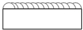
50% overlap single layer cladding
Three sets of welding current and welding voltage were selected, keeping travel speed constant. Three different rates of heat inputs were taken into consideration to get total nine experiments. The performance of the clad part was evaluated on the basis of corrosion resistance and hardness. In one previous experiment, Saha et al. observed the increase in hardness from 87 HRB (for low alloy base metal) to a hardness of 35-38 HRC (for Duplex Stainless Steel clad layer) during a cladding experiment by changing heat input34). Parameters chosen for the experiments are shown in Table 3.

Parameters of cladding experiment
3. Heat Input
Heat input plays a significant role in weld cladding. Proper heat input ensures proper penetration, favourable fusion and sufficient bonding in cladding. Heat input is a useful tool in evaluating welding procedure within a given process. Cooling rate, weld size and material properties may all be influenced by heat input1). Heat input was calculated by using equation (1).
Where, Q = Heat input (kJ/mm)
V = Voltage (V)
I = Current (A)
S = Travel speed (mm/min)
η = Efficiency for gas metal arc welding process, that is taken to be 0.827).
4. Corrosion Test
Eighteen number (nine numbers from 1st replication cladded specimens and nine numbers from 2nd replication cladded specimens) of test samples of size 15×15×25mm were prepared from clad plates (one test sample from each cladded specimen). A non-standard corrosion test, a special form of ASTM G48, was performed in this work. Previously, Woollin performed one non-standard pitting corrosion test for duplex stainless steel, that was different from ASTM G48 by the solution preparation, size of specimen and preparation method35). Test samples were polished using different grades of emery papers (200, 400, 600, 800 and 1000) followed by final polishing in the disc polishing machine. Each test sample was weighed by digital weighing machine with a least count of 0.001gm. Top surface area of each test sample was then measured using a digital slide caliper and the remaining surface area was covered by Teflon. The corrosion test solution was a mixture of ferric chloride (FeCl3, 6H2O), hydrochloric acid (HCl) and distilled water. Each sample was immersed in the solution for 24 hours (Fig. 5). Test samples were then taken out of the solution and washed with water. Samples were weighted again and the difference in weight of each sample before and after the test was determined27). Corrosion rate was calculated using equation (2). Fig. 2 shows corrosion test arrangement.
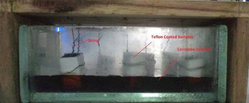
Corrosion test set-up
Microstructure of sample CS2

Microstructure of sample CS6

Microstructure of sample CS4

Microstructure of sample CS5

Microstructure of sample CS9

Microstructure of sample CS8

Microstructure of sample CS7
where,
W = Weight loss (gm)
A = Exposed area (m2)
T = Exposed time (hr)
5. Metallographic Study
For metallographic study, total number of eighteen test samples (nine samples each from 1st and 2nd replication) having size (15mm x15mm x 25mm) were prepared. At first, each sample was polished by using a belt grinder (Grade of belt used 60, 80 and 120), and then polished by using six grades of emery paper (200, 400, 600, 100 and 1200). Finally the samples were polished on velvet cloth using alumina suspension as abrasive material to obtain mirror finish by using Disc grinding cum Polishing Machine. Samples were then etched by waterless Kalling’s reagent and Ralph’s reagent one after another. Microstructure examination was carried out using metallurgical microscope. The photographs of the microstructure were taken at 200x magnification.
6. Results and Discussions
6.1 Corrosion Properties of Cladding
Table 4 shows the corrosion rate of the base plate after performing corrosion test for 24 hours. The result shows that base plate has naturally more corrosion than clad samples. Table 5 shows the results of corrosion test of clad samples responding to two replicated experiments.
Table 5 shows the corrosion rate of the clad samples of two replicated experiments. The results show that corrosion rate is different for the three different heat input conditions. Variation in corrosion rate is observed against application of the same heat input with varying welding current and welding voltage.
Fig. 3a and 3b show 3D surface plot and contour plot of corrosion rate against current and voltage. By these plots, variation of corrosion rate is shown against different current and voltage in a combined way. From these two plots, it can be clearly observed that corrosion resistance of clad parts increases in low current and low voltage simultaneously.
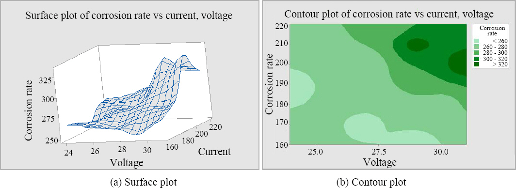
3D plot of corrosion rate against weld current and welding voltage
Different heat inputs used for cladding and corresponding corrosion rate of two replicated experiments are plotted in a graph is shown in Fig. 4. The figure shows that corrosion rate increases on the whole with increasing heat input. Results of corrosion rate of clad samples are found more or less similar among the two replicated experiments.
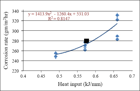
Plot of variation of corrosion rate with heat input
Fig. 4 also shows best fit quadratic polynomial trend line along with the equation. The graph shows the value of R2 as 0.8147 that indicates 81.47% of the known variables are explainable among all the variables.
6.2 Microstructure of Cladding
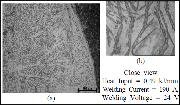
Microstructures of duplex stainless steel cladding on low alloy steel are shown under different parametric combinations in Fig. 5i through Fig. 5ix. The combination of parameters is chosen in such a way that the heat input is kept almost the same for the set of three experiments successively, i.e. the heat input of 1st three, 2nd three, and 3rd three experiments are kept the same, and the corresponding values are 0.49 kJ/ mm, 0.57 kJ/mm, 0.66 kJ/mm respectively. The etchant used was Ralph’s reagent and Waterless Kalling’s reagent one by one. The magnification is taken as X200.

Microstructure of sample CS3

Microstructure of sample CS1
Different microstructures obtained from different cladded test pieces broadly exhibit two common phases: austenite and ferrite. The blackish austenite phase is surrounded by whitish ferrite phase. As heat input increases, grains require more time to cool, and thus, grains get more scope to increase its size. From various microstructures, it can be observed that with increase in heat input, the grain growth increased for both austenitic and ferrite phase. And also the amount of austenite increased and ferrite decreased with increasing heat input. This phenomenon explains the increase in corrosion rate with heat input.
The consumable electrode used is duplex stainless steel that contains C 0.02%, Si 0.7%, Mn 1.01%, Cr 22.5%, Mo 2.91%, Ni 9.09%, N 0.125%. The Chromium equivalent and Nickel Equivalent 1 for Duplex Stainless Steel are given as follows:
For the duplex stainless steel used in this case, the Cr and Ni equivalents are computed as 26.46 and 13.94 respectively. Cr equivalent and Ni equivalents are nothing but the ferritizer and austenizer respectively, i.e. they create ferrite phase and austenite phase simultaneously. The austenite - ferrite boundary are very well defined in the microstructure.
In this work, microstructure of minimum heat input (0.49 kJ/mm) has less austenite phase than the microstructure of 0.57 kJ/mm and 0.66 kJ/mm heat input conditions. Microstructure at maximum heat input (0.66 kJ/mm) condition has less ferrite phase. Results of corrosion testing clearly indicate that minimum corrosion rate occurred at low heat input (0.492 kJ/mm) of both replications contain more austenite phase. On the other hand, maximum corrosion rate occurred at high heat input (0.66 kJ/mm) of both replications those contain less ferrite phase.
6.3 Regression Analysis
Linear regression does not satisfy the scatterings of the results obtained from corrosion test and the value of R2 is quite low. For better understanding of the relationship between corrosion rate and heat input polynomial or non-linear regression with 2 degree was chosen which yielded better result with satisfactory high value of R2 which was 0.8147.
The regression equation is
CAvg = 737.1 - 2007 Q + 2082 Q2
Where, Q = Heat input in kJ/mm
CAvg = Average corrosion rate
The value of R2 increases in case of 2nd degree equation than linear relation. But it does not increase appreciably if the degree of equation increases. Moreover it is very difficult to maintain high degree relation at real working condition. Values of corrosion rate yielded from proposed model produces less error in comparison with experimental values.
Table 6 shows analysis of variance of the obtained relationship between heat input and corrosion rate. It shows summation of square of response, degree of freedom, mean square, F value and p value. As the value of F increases and value of p decreases, the probability of favourable outcome will be significant. In this work, quadratic equation is developed that gives decreasing p value and more F value indicating the quadratic relation between heat input and corrosion rate to be significant at a 95% confidence level.
7. Conclusion
From the present experimental investigation on duplex stainless steel cladding by FCAW welding on low alloy steel specimens, following conclusions may be drawn:
• Results of corrosion test clearly indicate that within the experimental domain, corrosion resistance of the clad part decreases with increasing heat input. Minimum corrosion rate is obtained in the present investigation at 0.49 kJ/mm heat input with 170A weld current, 27V weld voltage and 7.5 mm/s weld torch travel speed. Also for a particular heat input, corrosion rate is found to vary with different weld current.
• Microstructure of duplex stainless steel cladding shows presence of austenite phase, and ferrite phase. For an increase in heat input, the microstructure of clad part sacrifices more amount of ferrite phase that exhibits more amount of corrosion.
• 2nd degree polynomial equation has been successfully generated between heat input and corrosion rate that agrees well with the experimental data with less error within this experimental domain.
ANOVA table suggests that the relation obtained from corrosion rate corresponding to different heat input is significant at 95% confidence level.
Acknowledgements
The authors state that for the present research work, necessary fund has been provided by Kalyani Govt. Engineering College, Govt. West Bengal, Kalyani, India.