1. Introduction
Aluminum and its alloys are widely used in automotive, military and aerospace industries
1). They have high specific strength and corrosion resistance. On the other hand, magnesium alloys are the lightest structural alloys that are used in various industries. Complex structure of aluminum-magnesium used in engines and components of spacecrafts
2). Therefore, achievement to reliable bonding between dissimilar metals of aluminum/magnesium can be used in different functions
3). At the moment, access to bonding between these two metals is very difficult. Intermetallic compounds that seriously affect the performance of the bonding are inevitably formed in the joint during welding process. In this regard, fusion joining and solid state methods are used to join the two alloys. The main challenge in bonding magnesium and aluminum lies in the formation of detrimental Mg-Al intermetallic compounds (IMCs) at the joint interface. These Mg-Al binary IMCs include Mg
17Al
12 and Mg
2Al
34). These hard and brittle compounds are known to cause the poor performance in the joints
1-4). In particular, the bonding of Al and Mg alloys is not possible by classical welding methods because of unexpected phase formation in the joint area. Among solid-state welding techniques for joining such alloys, the following processes could be cited: friction welding, explosive welding, transient liquid phase bonding and diffusion bonding
5-7). Friction-stir welding
8-12) of Mg-Al can achieve relatively high joining strength comparing other methods, but for the direct contact of base Mg and Al, there are also Mg-Al intermetallic compounds in the joints.
As mentioned, FSW was used to eliminate the intermetallic reaction layer, but the IMCs could only be reduced. There are two approaches to reduce the IMCs. One approach, used in our previous research is to conduct submerged FSW (SFSW) underwater or under liquid nitrogen
13). The other approach is Diffusion bonding. Diffusion bonding is a widely used technology for creating similar and dissimilar joints from challenging materials. These materials are usually joined at elevated temperatures, between 0.5 and 0.8 of the absolute melting point, using a defined contact pressure with a joining time ranging from a few minutes to a few hours
6). Vacuum diffusion bonding can precisely regulate heating temperature and holding time, and then control the forming of intermetallic compounds
3).
Formation mechanisms of liquid and intermetallics were investigated by some researchers, and the thermal behavior during the FSW was measured. Firouzdor et al. confirmed that that the peak temperature was slightly below the eutectic reaction because the thermocouples were pushed downward during welding
1). They also confirmed that the solidified droplets melted at 436 and 449 ┬░C by differential scanning calorimetry, nearly identical to the eutectic temperatures.
Many experimental studies have been done for diffusion bonding
4,5,14,15). The outstanding process parameters in diffusion bonding are: bonding temperature, bonding pressure, holding time and surface roughness of the alloys to be joined It has been found that bonding temperature has a greater influence on shear strength and bonding strength of the joints followed by bonding pressure, holding time, and surface roughness
14).
Generally, nowadays attentions are towards using diffusion welding of dissimilar materials directly, without using an interlayer, minimizing the plastic deformation and maximizing the strength of the joints
2). For this reason in this study the bonding of aluminum and magnesium alloys is investigated by diffusion welding method without the use of interlayer and in an appropriate pressure and time. No literature was found on comparison of details of microstructural evolution, during dissimilar FSW and Diffusion bonding of Al and Mg. The present study examines microstructural features in dissimilar FS and Diffusion weld of Al alloy 5083 and Mg alloy AZ31, at similar peak temperature. Microstructural and mechanical properties of the joints were analyzed.
2. Experimental procedure
The base materials used in this study were 3 mm thick sheets of 5083 Al alloy with the composition of Al-4.6 Mg-0.2Si-0.3Fe-0.1Cr-0.6Mn (weight percent) and AZ31C- O Mg alloy with the composition of Mg-5.3Al-3.1Zn- 0.2Mn (weight percent).
For FSW, the rotating pin traveled along the butt line between the two base materials. The optimized parameters used in our FSW experiment were a rotation speed of 400 rpm (low rotational speed to avoid liquation cracking) and travel speed of 50 mm/min. The welding tool rotated counterclockwise when viewed from above, and tilted 3┬░ forward. The tool shoulder was 20 mm in diameter and concave. The pin was threaded, 7 mm in diameter and 2.8 mm in length. Depth of penetration of the pin was 0.2 mm. The pin was made of H13 steel. Thermal measurements were made using four K-type thermocouples embedded in the workpiece. The locations of the thermocouples with respect to the workpiece are indicated in
Fig. 1. Four K-type thermocouples with a stainless steel sheath of 1 mm outer diameter, each were placed in a 1-mm diameter square groove at the bottom surface of the workpiece. A computer-based data acquisition system was used to record the temperatures during FSW at a frequency of 1 Hz. Prior to initiating each weld, the rotating collar came in to contact with the plates and was held in this position for approximately 10 s before commencing the weld. Specimens for OM were cut perpendicular to the welding direction.
Fig.┬Ā1
Schematic diagram of workpiece dimensions and thermocouple situation used for FSW

For Diffusion bonding, Square shaped specimens (50 mm ├Ś 50 mm) were machined from plates of 3 mm thickness magnesium (AZ31C-O) and aluminum (AA5083) alloys. The specimen surfaces were prepared by conventional grinding techniques with final grinding on 1200# emery paper. The specimens were ultrasonically cleaned in an acetone bath to remove adhered contaminants and then dried in air. DB was carried out under a constant bonding pressure of 1 MPa and at the bonding temperature of 435 ┬░C for a bonding time of 60 min. Vacuum pressure was less than 6├Ś10-3 Pa. In the bonding process, heating rates of the experiment were kept at 15 ┬░C/min, the assemblies were cooled in the processing chamber under vacuum. The bonding specimen was sectioned by a cutting machine.
Following FSW and DB, cross-sections of two specimens were observed by optical microscopy (OM). The specimens for OM were etched in a 5 ml acetic acid+5 g picric acid+10 ml water+100 ml ethanol solution for revealing Mg side of the weld. The chemical composition of the second phases in the weld zones was analyzed by SEM equipped with EDS analysis system.
Additionally, second phases in the stir zone of FSW and interface zone of DB weld were identified by the X-ray diffraction (XRD) method. Samples for XRD were made by powdering blocks of stir zone of FSW weld and interface zone of Diffusion bond weld that mainly contained second phases. The blocks were carefully cut from a region containing only the second phases. However, they actually contained a small volume of the two base materials.
A Portable Hardness Testing by the ultrasonic contact impedance method (ASTM A1038)
16) was used to obtain Vickers microhardness measurements throughout the weld zones. Measurements were taken along 2 cm on the cross section (stretching from one base material, through the transition and weld regions, and into the other material) using a load of 10 N. The shear strength of the specimen was measured according to ASTM standard D1002ŌłÆ99 at a cross-head speed of 1 mm/min.
3. Results
The temperature profiles for friction stir weld and Diffusion bond weld samples are shown in
Fig. 2. The process parameters for FSW, were pin rotation speed of 400 rpm and travel speed of 50 mm/min and for Diffusion bond weld, were bonding temperature of 435 ┬░C and bonding time of 60 min.
Fig. 2 profiles, show that FSW and DB initiated at 25 ┬░C. The rotating collar began stirring against the top of FSW sample at the point indicated as ŌĆ£contactŌĆØ in
Fig. 2. Approximately 10 s later, the weld was allowed to commence. It is apparent that after start of welding process, an increase in temperature is seen (red arrow). As the rotating pin passed by the thermocouple, the temperature at this point in the sample rose to a maximum 435 ┬░C in advancing side.
Fig.┬Ā2
Temperature profiles for friction stir weld and di- ffusion bond weld samples. Process parameters were pin rotation speed of 400 rpm and travel speed of 50 mm/min for FSW and bonding temperature of 435 ┬░C and bonding time of 60 min for diffusion bond weld

Fig. 3a shows the surface appearance of the FSWed plates. Defect-free welds were successfully obtained for the 400 rpm sample. In addition, the surface morphology of the SZ became smooth for this sample. This result show that rotation speed of 400 rpm and travel speed of 50 mm/min are optimum welding parameters for the dissimilar FSW between AZ31 and A5083 alloy plates.
Fig.┬Ā3
(a) Surface appearance (b) Microstructure of Al/Mg interface (c) SEM micrograph and EDS results of Al/Mg interface microstructure (d) Cracks formation in interface of Al alloy and Mg alloy in stir zone for friction stir weld of Al 5083 to MgAZ31
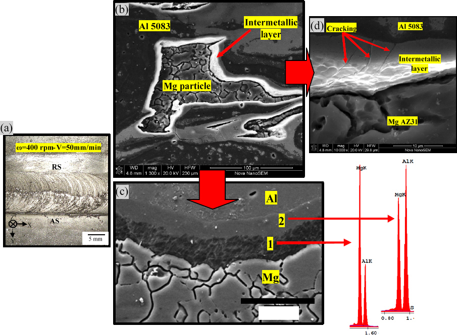
Fig. 3b illustrates the microstructure of the Al/Mg interface for the friction-stir welded specimen. The static grain growth can be clearly seen in the recrystallized Mg grains in this zone. The average grain size of Mg in this zone is 20 ┬Ąm.
Fig. 3c shows that significant intermetallic material exists in the stir zone as light-etching and dark-etching phases. The lighter etching layer is on the Al side and the darker one is on the Mg side. The latter, because of its higher Mg content, is much more susceptible to corrosion and is preferentially etched out as dark pits. This region (
Fig. 3c) was studied by means of EDS. EDS analysis of selected regions in
Fig. 3c is represented in
Table 1. SEM observations indicated that the interface zone of the Mg/Al joint included the transition region on the Mg substrate (
Fig. 3c, region 1) and the transition region on the Al substrate (
Fig. 3c,
Fig. 3 region 2). Al and Mg distributions in these regions analyzed by EDS are shown in
Table 1. Regions 1 and 2 have different chemical compositions; i.e., region 1 has lower Al and higher Mg contents than region 2. According to a phase diagram of the aluminum-magnesium system
17) and
Fig. 3, layers of intermetallic phases are expected to be formed. The average thickness of the interaction layers in FS weld is 45 ┬Ąm. The new phases are Al
12Mg
17 and Al
3Mg
2 intermetallics. These phases are all brittle compounds, which are the main reason for the formation of the weld crack. Both Al
12Mg
17 and Al
3Mg
2 phases have been reported in the literature as products of solid-state joining
1,18,19).
Fig. 3d shows many cracks in these phases, indicating a brittle weld owing to intermetallics.
Table┬Ā1
EDS analysis (wt.%) of selected regions for friction stir welded sample shown in Fig. 3c
|
Al |
Mg |
|
1 |
45.88 |
54.12 |
|
2 |
58.75 |
41.25 |
A transverse cross section of dissimilar diffusion bond is presented in
Fig. 4a. The weld shows no large defects, but contains a melted-and-solidified eutectic structure in the weld center.
Fig. 4b shows higher magnification BSE micrograph of the interface. EDS analysis of selected regions in
Fig. 4b is represented in
Table 2. The joint consists of three different zones: (1) a hypo-eutectic structure in the middle of the joint (regions A. B) and (2, 3) a two layer structure, between the eutectic and the Al base (regions C. D). According to BSE image (
Fig. 4b), the phases in the eutectic region can be classified into two types: Dark (Point A) and bright (Point B) phases. EDS results (
Table 2) illustrate that Mg is the main element in the dark phase. The results suggest that the bright and dark phases in
Fig. 4b are the intermetallic compound Al
12Mg
17 and the Mg solid solution, respectively. An intermetallic Al
12Mg
17 phase is found to grow epitaxially from the Mg base in cellular dendritic mode (region C in
Fig. 4b). The phase in region D seems to be Mg
2Al
3, based on the chemical composition.
Table┬Ā2
EDS analysis (wt.%) of selected regions for diffusion bond welded sample shown in Fig. 4b
|
points |
Element composition (wt.%) |
Possible phase |
|
Mg |
Al |
Zn |
|
A |
92.6 |
6.7 |
0.7 |
Mg(ss, Al) |
|
B |
64.5 |
35.4 |
0.1 |
Mg17Al12
|
|
C |
62.18 |
37.12 |
0.7 |
Mg17Al12
|
|
D |
39.7 |
60.1 |
0.2 |
Mg2Al3
|
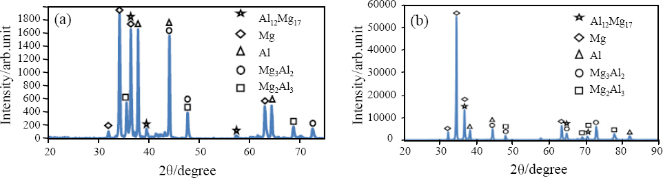
The XRD spectrums of the powders of two specimens, obtained in the irregular shaped region of DB weld and stir zone of FS weld, are indicated in
Fig. 5. Large peaks of intermetallic compound Al
12Mg
17 are detected, though this Fig. contains some peaks obtained from matrices of Al and Mg alloys which were mixed into the powder of the second phases. The XRD spectrum confirms that the irregular shaped and stir zone regions of the dissimilar welds contain a large volume of the intermetallic compound Al
12Mg
17.
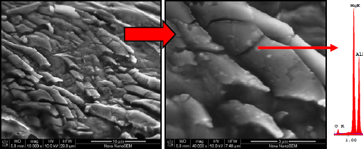
Fig.┬Ā4
(a) Low magnification micrograph (b) Higher magnification BSE micrograph of the irregular shaped region of dissimilar DB weld of Al 5083 to MgAZ31 at the bonding temperature of 435 ┬░C for a bonding time of 60min

Fig.┬Ā5
XRD spectrums of the powders of two specimens obtained in the (a) Stir zone of FS weld (b) Irregular shaped region of DB weld
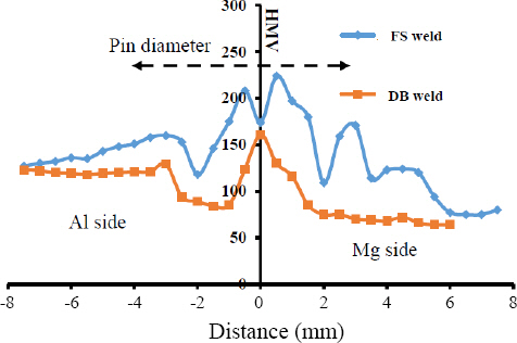
The Vickers microhardness (HMV) profiles in the mid thickness cross sections of specimens, across the irregular shaped region of DB weld and stir zone of FS weld are shown in
Fig. 6. Some fairly high hardness values are observed in the interfaces of the FS and DB welded specimens. Base materials of Al and Mg alloys have average hardness values of 128 and 72 Hv, respectively, while the stir zone and irregular shaped region in the weld center have hardness values between 120 and 224Hv. This higher hardness is due to the intermetallic compound Al
12Mg
17.
Fig.┬Ā6
Vickers hardness profiles in the mid thickness cross sections of specimens, across the irregular shaped region of DB weld and stir zone of FS weld
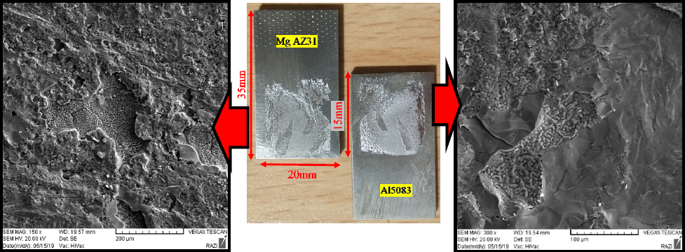
Shear strength of the DB welded specimen was determined by the single lap shear test. Illustration of the joint geometry prepared for performing the shear strength tests is shown in
Fig. 7. The shear strength of joint corresponding to DB welded specimen is 43.2 MPa. The fracture surface for Al5083 and Mg AZ31 sides is illustrated in
Fig. 7. The fractographs show a brittle fracture mode. In this specimen, fracture occurs in the diffusion area, because this area includes brittle intermetallic compounds.
Fig.┬Ā7
The dimensions of shear strength test, fracture zone and SEM fractographs of the surfaces of DB welded specimen
The tensile strength of joint corresponding to FS welded specimen was 51.3 MPa. Surface morphology and EDS analyses of fracture surface of the joint are shown in
Fig. 8. The fracture occurred preferentially along the brittle and weak intermetallic layers. The resultant fracture surface shows the cleavage-type brittle fracture, as is shown in the SEM image in
Fig. 8. The EDS analyses indicate the large Mg
17Al
12 particles are the major cause of fracture for this joint.
Fig.┬Ā8
Fracture surface morphology and EDS analyses of the FS welded specimen
4. Discussion
In FSW temperature profile shown in
Fig. 2, thermocouple in the advancing side (T1) shows higher temperature in comparison with the retreating side thermocouple (T3). Furthermore, the second thermocouple in advancing side (T2) shows higher temperature in comparison with retreating side thermocouple (T4). Clearly, the material on the advancing side experiences a longer flow distance and thus reaches higher temperatures than that on the retreating side.
Thermal cycle of the FSW specimen welded in air shows a distinct plateau at about 430 ┬░C, lasting for about 8 s (
Fig. 2). At the travel speed of 50 mm/min, the distance corresponding to 8 s is about 7mm, which is the pin diameter. The presence of the temperature plateau indicates that the temperature at each thermocouple remained constant as the pin passed it. It further indicates that a eutectic reaction occurred, and kept the temperature constant as the pin passed by.
As can be seen in temperature profiles of
Fig. 2 the bonding temperature of 435 ┬░C, used in this study is equivalent with maximum temperature, experienced during FSW with rotation speed of 400 rpm and travel speed of 50 mm/min.
According to the Al-Mg phase diagram, when Al and Mg are heated up together, Al
3Mg
2 and Al
12Mg
17 intermetallic compounds may form; the former on the Al side and the latter on the Mg side. Upon further heating, the eutectic reaction Mg+Al
12Mg
17ŌåÆL occurs at the eutectic temperature 437 ┬░C and the eutectic reaction Al+ Al
3Mg
2ŌåÆL at the eutectic temperature 450 ┬░C. This liquid formation is called constitutional liquation
11). The eutectic temperatures 437 and 450 ┬░C are about 200 ┬░C below the melting points of Al and Mg, and they can be reached easily during FSW to form liquid films along the interface, and hence, lead to cracking
12).
Fig. 4 shows metallographic evidence confirming local melted film formation within the stir zone of Mg/Al FS welded joint.
Dissimilar FS and DB weld of Al alloy 5083 and Mg alloy AZ31 produced the intermetallic compound Al
12Mg
17 in the weld center, which resulted in significantly higher hardness in the weld compared to the base material. Results of OM and EDS show that a mixed microstructure of magnesium and aluminum alloys was formed near the bonded interface during the FSW (
Fig 4). This result proves that the rotating tool induces the plastic flow between the base metals by the mechanical stirring action. On the other hand, Sato et al.
11) have reported that a eutectic microstructure was formed in the SZ with some pores by constitutional liquation through a eutectic reaction between aluminum and magnesium. In this study eutectic microstructure was formed. This result demonstrates that the SZ was heated up to a temperature above the liquidus line during the FSW. Based on results dissimilar FS weld should be exposed to peak temperatures higher than 435 ┬░C during the stirring. The peak temperature is sufficient for mutual diffusion between Al and Mg atoms. Additionally, the diffusion rates should be higher than that in the static condition, because Yashan et al.
20) suggest in a previous study on friction welding of 1100 Al and type 316 stainless steel that the diffusion is enhanced during plastic deformation with a high strain rate. The binary Al-Mg phase diagram
17) shows eutectic temperatures of 437┬░C and 450┬░C. Intensive mutual diffusion can form a liquid-phase constitutionally when the material is constantly held at temperatures higher than 435 ┬░C. The general disposition of microhardness profiles (
Fig. 6), shows that the hardness of FS welded specimen is higher than DB welded specimen. This can be an explanation to the formation of intermetallic compounds at the joint center and higher diffusion rates than that in the static condition.
In the solid state method, formation rate of intermetallic phases depends on the diffusion rate and reaction rate in the interface. Diffusion rate depends on factors such as temperature, grain size, migration of grain boundaries and dislocations density. Formation of these compounds during diffusion welding is in this way that at first both sides with different rates diffuse together and then a supersaturated solid solution is formed. The crystal nucleation of new phases is formed in defects where the concentration of the diffused element is high crystal nucleation of intermetallic compounds will grow along the interface. Many of these grown nucleations come together and normally grow longitudinally. After that, the crystal nucleations of the second intermetallic compound will form and grow in the interface. The ╔Ż-Al12Mg17 phase was observed first. It is expected that the phase containing the greater proportion of the fastest diffusing species will be the phase to nucleate first. In this system, the activation energy for diffusion is lower for magnesium in aluminum than it is for aluminum in magnesium and magnesium is, therefore, the fastest diffusing of the two species. As the ╔Ż-Al12Mg17 phase is magnesium rich, it would therefore be expected to form before the ╬▓-Al3Mg2 phase.


 PDF Links
 PubReader
 ePub Link
 Full text via DOI
 Download Citation
 Print
Print


