


1. ņä£ ļĪĀ
ņ£Āļ¤Į ņØśĒÜīņÖĆ EU ņØ┤ņé¼ĒÜīļŖö ņ£Āļ¤Į ņŚ░ĒĢ®ņŚÉņä£ņØś ņāłļĪŁĻ▓ī Ļ░£ļ░£ļÉśļŖö ņ░©ļ¤ēņŚÉ ļīĆĒĢ┤ CO2 ļ░░ņČ£ĻĘ£ņĀ£ļź╝ ņŗżņŗ£ĒĢśĻ│Ā, 2020ļģäĻ╣īņ¦Ć ņŖ╣ņÜ®ņ░©ņØś CO2Ļ░ĆņŖż ļ░░ņČ£ļ¤ēņØä 95 g/kmļĪ£ Ļ░Éņåīņŗ£ĒéżĻĖ░ļĪ£ ĒĢśņśĆļŗż1). ņŚöņ¦äĒÜ©ņ£©ņØś Ē¢źņāü ļśÉļŖö Ļ│ĄĻĖ░ņĀĆĒĢŁņØś Ļ░Éņåīļź╝ ĒåĄĒĢ£ ņŚ░ļŻīĒÜ©ņ£© Ē¢źņāüņŚÉļŖö ĒĢ£Ļ│äĻ░Ć ņĪ┤ņ×¼ĒĢśĻĖ░ ļĢīļ¼ĖņŚÉ, ņ░©ņ▓┤ņØś ļ¼┤Ļ▓īļź╝ Ļ░Éņåīņŗ£Ēéżņ¢┤ ĒÜ©ņ£©ņØä ņ”ØļīĆĒĢśĻ│Āņ×É ĒĢśļŖö ņŗ£ļÅäĻ░Ć Ļ│äņåŹļÉśĻ│Ā ņ׳ļŗż2). ņŗżņĀ£ļĪ£ ņ░©ļ¤ē ļ¼┤Ļ▓īĻ░Ć 100 kg Ļ░ÉņåīĒĢśļ®┤ CO2 ļ░░ņČ£ļ¤ēņØĆ 6 g/km Ļ░Ćļ¤ē Ļ░ÉņåīĒĢśļ®░ ņŚ░ļ╣äļŖö ņĢĮ 0.5 L/100 km ņĀłņĢĮļÉ£ļŗżĻ│Ā ļ│┤Ļ│ĀļÉ£ ļ░ö ņ׳ļŗż3,4). Ļ▓Įļ¤ēĒÖöļź╝ ņ£äĒĢśņŚ¼ ņ┤łĻ│ĀĻ░ĢļÅäĻ░Ģ, ņĢīļŻ©ļ»ĖļŖä, CFRP(Carbon Fiber Reinforced Plastics) ļō▒ņØś ļŗżņóģņåīņ×¼ņØś ņĀüņÜ®ļ╣äņ£©ņØĆ ņĀÉņ░© ĒÖĢļīĆļÉśĻ│Ā ņ׳ņ£╝ļ®░, ĻĘĖ ņżæ ļ╣äĻ░ĢļÅäĻ░Ć ļåÆņØĆ CFRP5,6) ņÖĆ ņŚ░ņä▒ņØ┤ ņÜ░ņłśĒĢ£ ņĢīļŻ©ļ»ĖļŖäņØĆ ĻĖ░ņĪ┤ ņ▓ĀĻ░Ģņåīņ×¼ņØś ļīĆņ▓┤ņ×¼ļĪ£ņŹ© ņĀ£ņĢłļÉśĻ│Ā ņ׳ļŗż7). ļŗżņóģņåīņ×¼ņØś ņĀüņÜ®ļ╣äņ£©ņØ┤ ņ”ØĻ░ĆĒĢ©ņŚÉ ļö░ļØ╝, Ļ░üĻĖ░ ļŗżļźĖ ĒŖ╣ņä▒ņØä Ļ░Ćņ¦ĆļŖö CFRPņÖĆ ņĢīļŻ©ļ»ĖļŖä ņĀæĒĢ®ņØĆ ņ░©ļ¤ēņØś ņĀ£ņ×æņŚÉ ņ׳ņ¢┤ņä£ ĒĢäņłśņĀüņØĖ ļČĆļČäņØ┤ ļÉśņŚłļŗż. ĒĢśņ¦Ćļ¦ī CFRPļŖö ņĢäĒü¼ņÜ®ņĀæ Ēś╣ņØĆ ņĀÉņÜ®ņĀæĻ│╝ Ļ░ÖņØĆ ĻĖ░ņĪ┤ ņÜ®ņ£ĄņÜ®ņĀæņØś ņĀüņÜ®ņØ┤ ļČłĻ░ĆļŖźĒĢśĻĖ░ ļĢīļ¼ĖņŚÉ8), ņĀæņ░®ņĀ£ļéś ļĖöļØ╝ņØĖļō£ ļ”¼ļ▓│, ļ│╝ĒīģĻ│╝ Ļ░ÖņØĆ ĻĖ░Ļ│äņĀü ņ▓┤Ļ▓░ ņżæņŗ¼ņØś ļ╣äņÜ®ņĀæļ▓ĢņØ┤ ņĀ£ņĢłļÉśĻ│Ā ņ׳ļŗż. ņĀæņ░®ņĀ£ļŖö CFRPņÖĆ ņĢīļŻ©ļ»ĖļŖäĻ░äņØś ņĀæĒĢ® ņŚ░ĻĄ¼ņŚÉņä£ ņĀüņÜ®ļÉśĻ│Ā ņ׳ļŖö ļ│┤ĒÄĖņĀüņØĖ ļ░®ļ▓Ģ ņżæ ĒĢśļéśņØ┤ņ¦Ćļ¦ī, ņĀæņ░®ņĀ£ļź╝ ļÅäĒżĒĢśĻ│Ā Ļ▓ĮĒÖöņŗ£ĒéżĻĖ░ ņ£äĒĢ£ Ļ│ĄņĀĢņØ┤ ņČöĻ░ĆļÉśņ¢┤ņĢ╝ ĒĢśļŖö ļŗ©ņĀÉņØ┤ ņ׳ļŗż9,10). ļ│╝ĒŖĖ/ļäłĒŖĖ Ļ▓░ĒĢ®ņØĆ Ļ░Ćņן ņØ╝ļ░śņĀüņØĖ ĻĖ░Ļ│äņĀü ņĀæĒĢ® ļ░®ļ▓Ģ ņżæ ĒĢśļéśņØ┤ņ¦Ćļ¦ī, ĒÖĆ Ļ░ĆĻ│ĄņØä ņäĀĒ¢ēļÉśņ¢┤ņĢ╝ ĒĢĀ ļ┐Éļ¦ī ņĢäļŗłļØ╝ ĒÖĆĻ│╝ ĒÖĆ, ĒÖĆĻ│╝ ļ│╝ĒŖĖņØś ņĀĢļĀ¼ņØ┤ ņ¢┤ļĀżņøī ņ×ÉļÅÖĒÖöĒĢśĻĖ░Ļ░Ć ņ¢┤ļĀĄļŗż. ĒŖ╣Ē׳ CFRPļŖö ļé£ņéŁņ×¼ļĪ£ ĒÖĆ Ļ░ĆĻ│ĄņØ┤ ņŚ¼ĒāĆņØś ņåīņ×¼ļ│┤ļŗż ņ¢┤ļĀĄĻĖ░ ļĢīļ¼ĖņŚÉ ļ│╝ĒīģņØś ņĀüņÜ®ņØ┤ ļé£ĒĢ┤ĒĢśļŗż11-13).
SPR(Self-Piercing Rivet)ņØĆ ņāü/ĒĢśļČĆņØś ĒÖĆļŹöļĪ£ pre- clamping ĒĢśņŚ¼ ļīĆņāüņåīņ×¼ļź╝ Ļ│ĀņĀĢņŗ£Ēé© Ēøä, ņāüļČĆ ĒÖĆļŹö ņĢłņØś punchļź╝ ņé¼ņÜ®ĒĢśņŚ¼ rivetņØä ļłīļ¤¼ ļ│äļÅäņØś ĒÖĆ Ļ░ĆĻ│ĄņØ┤ ņŚåņ¢┤ļÅä ņĀæĒĢ®ņØ┤ Ļ░ĆļŖźĒĢ£ ĻĖ░Ļ│äņĀü ņ▓┤Ļ▓░ļ░®ļ▓ĢņØ┤ļŗż. PunchņŚÉ ņØśĒĢ┤ ļłīļĀżņ¦ä rivetņØĆ ņāüĒīÉņØä Ļ┤ĆĒåĄĒĢ£ ļÆż ĒĢśĒīÉ ņĢäļלņ¬ĮņØś dieņØś ĒśĢņāüņŚÉ ļ¦×Ļ▓ī rivet ļŗżļ”¼Ļ░Ć ļ│ĆĒśĢļÉśļ®░ ņāüĒīÉĻ│╝ ĒĢśĒīÉņØä ņ▓┤Ļ▓░ĒĢśĻĖ░ ļĢīļ¼ĖņŚÉ ņä▒ĒśĢĻĖ░ļ░śņØś ņĀæĒĢ® ĻĖ░ņłĀļĪ£ ļ│╝ ņłś ņ׳ļŗż. ņĀæņ░®ņĀ£ņÖĆ ļ│╝ĒŖĖ/ļäłĒŖĖ Ļ▓░ĒĢ®ņŚÉ ļ╣äĒĢ┤ņä£ SPR ņĀæĒĢ®ļ░®ļ▓ĢņØĆ ņĀæĒĢ®Ļ│╝ņĀĢņŚÉņä£ ņŚ┤Ļ│╝ ļ│ĆĒśĢņØ┤ ņŚåņ£╝ļ®░ ņāüņØ┤ĒĢ£ Ļ░ĢļÅäņØś ņåīņ×¼ļź╝ ņĀæĒĢ®ņØ┤ Ļ░ĆļŖźĒĢśļŗż. ĒÖĆ Ļ░ĆĻ│ĄņØ┤ ĒĢäņÜö ņŚåĻ│Ā, Ļ│ĄņĀĢņŗ£Ļ░äņØ┤ ņ¦¦ņ£╝ļ®░ ļČłĒĢäņÜöĒĢ£ ļČĆņé░ļ¼╝ņØ┤ ņāØĻĖ░ņ¦Ć ņĢŖļŖöļŗż. ļśÉĒĢ£ ĻĖ░ņĪ┤ ņĀÉņÜ®ņĀæ ņןļ╣äņÖĆ C ļ¬©ņ¢æņØś ĒöäļĀłņ×äņØ┤ Ļ░ÖņĢä ĻĖ░ņĪ┤ ņäżļ╣äļź╝ ļīĆņ▓┤ĒĢśņŚ¼ ĒśĖĒÖśņØ┤ Ļ░ĆļŖźĒĢśļ®░, ņĀÉņÜ®ņĀæĻ│╝ ļ╣äņŖĘĒĢ£ Ļ░ĢļÅäņÖĆ ļåÆņØĆ Ēö╝ļĪ£ ĒŖ╣ņä▒ņØä Ļ░¢ļŖöļŗż14-16). ļĢīļ¼ĖņŚÉ SPRņØĆ CFRPņÖĆ Ļ░ÖņØĆ ļ│ĄĒĢ®ņ×¼ļŻīļź╝ ĒżĒĢ©ĒĢ£ ņØ┤ņóģņåīņ×¼ņØś ņĀæĒĢ®ņŚÉ ļ¦żņÜ░ ņ£Āļ”¼ĒĢśļŗż.
ĻĖ░ņĪ┤ņØś SPR ņŚ░ĻĄ¼ņŚÉņä£ C.G. Pickin17,18) ļō▒ņØĆ SPR ņĀæĒĢ®ņŗ£ rivet ļ░Å die ĒśĢņāüņØ┤ ņĀæĒĢ®Ļ░ĢļÅäņŚÉ ļ»Ėņ╣śļŖö ņśüĒ¢źņŚÉ ļīĆĒĢśņŚ¼ Ļ│Āņ░░ĒĢśņśĆņ£╝ļ®░, J.H. Bae19)ļŖö Ļ│ĄņĀĢļ│ĆņłśņØĖ ĒÄĆņ╣śņĢĢļĀźņØä ļ│ĆĒÖöĒĢśņŚ¼ ņĀĢņĀüĻ░ĢļÅäņŚÉ ļ»Ėņ╣śļŖö ņśüĒ¢źņØä ĒÖĢņØĖĒĢśņśĆļŗż. M. Louļō▒20-22) ņØĆ ĻĖłņåŹĻ│╝ ņĢīļŻ©ļ»ĖļŖäņØś Ļ░ĢļÅä, ļæÉĻ╗ś ļ░Å ņāü/ĒĢśļČĆ ĒīÉņ×¼ņØś ļ░░ņ╣śĻ░Ć ņĀæĒĢ®ĒŖ╣ņä▒ņŚÉ ļ»Ėņ╣śļŖö ņśüĒ¢źņØä ĒÖĢņØĖĒĢśņśĆļŗż. ĒĢ┤ļŗ╣ ņŚ░ĻĄ¼ņŚÉņä£ļŖö ĒĢśĒīÉņØś ļæÉĻ╗śĻ░Ć ļäłļ¼┤ ņ¢ćĻ▒░ļéś, ņŚ░ņä▒ņØ┤ ļé«Ļ│Ā Ļ░ĢļÅäĻ░Ć ļåÆņØĆ Ļ▓ĮņÜ░ rivetņØ┤ ņĀüņĀłĒ׳ ņ▓┤Ļ▓░ļÉśņ¦Ć ļ¬╗ĒĢśĻ│Ā ĻĖ░Ļ│äņĀü ĒŖ╣ņä▒ņØ┤ ņĀĆĒĢśļÉ£ļŗżĻ│Ā ļ│┤Ļ│ĀĒĢśņśĆļŗż. J. Kang23) ļō▒ņØĆ ņĀüņĀłĒĢ£ Ļ│ĄņĀĢļ│ĆņłśņØś ņĪ░ĒĢ®ņØä ĒåĄĒĢśņŚ¼ CFRPņÖĆ Al6111-T82ņØś ņåīņ×¼ļź╝ SPR ņĀæĒĢ®ņØä ņé¼ņÜ®ĒĢśņŚ¼ ņĄ£ļīĆ ņØĖņן ĒĢśņżæ 3.9 kNņØä ļÅäņČ£ĒĢśņśĆļŗż. ĻĘĖļ¤¼ļéś CFRPņÖĆ ņĢīļŻ©ļ»ĖļŖäņØś SPR ņĀæĒĢ®ņŚÉņä£ Ļ░Ćņן ņĀüĒĢ®ĒĢ£ rivetĻ│╝ dieņØś ņĪ░ĒĢ®Ļ│╝ ņŻ╝ņÜö Ļ│ĄņĀĢļ│ĆņłśņØĖ punch forceņØś ļ│ĆĒÖöņŚÉ ļö░ļźĖ ņĀæĒĢ®ĒĢśņżæņØś Ļ┤ĆĻ│äļź╝ ļ│┤ņØĖ ņŚ░ĻĄ¼ļŖö ļČĆņĪ▒ĒĢśņśĆļŗż.
ļö░ļØ╝ņä£ ļ│Ė ņŚ░ĻĄ¼ņŚÉņä£ļŖö SPRņØś ņĀæĒĢ® ĒÆłņ¦ł ĒīÉļŗ©ņØä ņ£äĒĢ┤ ņØ┤ņĀäņØś ņŚ░ĻĄ¼24,25) ņŚÉņä£ ņäżņĀĢĒĢ£ ņäĖ Ļ░Ćņ¦Ć ņĖĪņĀĢņØĖņ×ÉņØĖ ņāüĒīÉ ņ£äļĪ£ rivetņØ┤ ļÅīņČ£ ļÉ£ ĻĖĖņØ┤ņØĖ head height, ĒĢśĒīÉņŚÉņä£ rivet ļŗżļ”¼Ļ░Ć ļ▓īņ¢┤ņ¦ä ĻĖĖņØ┤ņØĖ interlock, ĒĢśĒīÉņØś ņ×öņŚ¼ ļæÉĻ╗śņØĖ bottom thicknessļź╝ ņĖĪņĀĢĒĢśņśĆļŗż. ņäĖ Ļ░Ćņ¦Ć ņĖĪņĀĢņØĖņ×Éļź╝ ĒåĄĒĢ┤ CFRP-ņĢīļŻ©ļ»ĖļŖä SPR ņĀæĒĢ®ņŗ£ Ļ░Ćņן ņĀüĒĢ®ĒĢ£ rivet-type, die-typeĻ│╝ punchĻ░Ć rivetņØä ļłäļź┤ļŖö ĒלņØĖ punch forceļź╝ ĒÖĢņØĖĒĢśņśĆļŗż. ļśÉĒĢ£ ņØĖņןĒĢśņżæņŗ£ĒŚśņØä ņŗżņŗ£ĒĢśĻ│Ā ņĖĪņĀĢņØĖņ×ÉņÖĆ ņØĖņןĒĢśņżæĻ│╝ņØś ņāüĻ┤ĆĻ┤ĆĻ│äļź╝ ĒÖĢņØĖĒĢśņśĆļŗż.
2. ņŗżĒŚśļ░®ļ▓Ģ
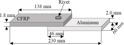
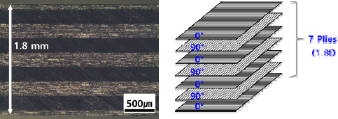
ņŗ£ĒŚśĒÄĖņØĆ KS C ISO 14273 ĻĘ£Ļ▓®ņØä ļö░ļØ╝ ņĀ£ņ×æļÉśņŚłļŗż.(Fig. 1) 1.8 mm ļæÉĻ╗śņØś ņŚ┤ Ļ▓ĮĒÖöņä▒ CFRPļź╝ ņāüĒīÉņŚÉ ļ░░ņ╣śĒĢśņśĆņ£╝ļ®░, ļæÉĻ╗śĻ░Ć 2.0 mmņØĖ Al5083-O ņåīņ×¼ļź╝ ĒĢśĒīÉņŚÉ ļ░░ņ╣śĒĢśņŚ¼ ņØ┤ņóģņåīņ×¼ ņĀæĒĢ®ņØä ņŗżņŗ£ĒĢśņśĆļŗż. ņŚ┤ Ļ▓ĮĒÖöņä▒ CFRPņØś ļŗ©ļ®┤Ļ│╝ ļ¬©ņŗØļÅäļź╝ Fig. 2ņŚÉ ļéśĒāĆļé┤ņŚłļŗż. CFRPļŖö (ņŻ╝) ĒĢ£ĻĄŁņ╣┤ļ│Ė ńżŠņŚÉņä£ ņĀ£ņ×æĒĢ£ ņĀ£ĒÆłņ£╝ļĪ£ņŹ©, Uni- directional form ĒśĢĒā£ņØś pre-pregļź╝ 0┬░ņÖĆ 90┬░ļĪ£ ĻĄÉņ░©ĒĢśņŚ¼ 7ņĖĄ ņĀüņĖĄĒĢ£ ļÆż ņśżĒåĀĒü┤ļĀłņØ┤ļĖīļĪ£ 3.02 kgf/cm2ņØś ņĢĢļĀźņŚÉņä£ 60~90ļČä ļÅÖņĢł Ļ▓ĮĒÖöņŗ£Ēé© Ļ▓āņØä ņé¼ņÜ®ĒĢśņśĆļŗż.
ņŗżĒŚśņŚÉ ņé¼ņÜ®ļÉ£ CFRPņÖĆ Al5083-O ņØś ļ¬©ņ×¼ņØĖņןĒÅēĻ░Ćļź╝ ņŗżņŗ£ĒĢśņśĆļŗż. ņŗ£ĒŚśĒÄĖņØĆ Fig. 3ņŚÉ ļéśĒāĆļéĖ ASTM E8M ĻĘ£Ļ▓®ņ£╝ļĪ£ ņĀ£ņ×æĒĢśņśĆļŗż.

Al5083-OņØś ļ¬©ņ×¼ņØĖņןĻ░ĢļÅä Ļ░ÆņØĆ 280 MPaņØ┤ļ®░, CFRPļŖö 0┬░ ļ░®Ē¢źņŚÉņä£ 1032 MPa, 45┬░ļ░®Ē¢źņŚÉņä£ 234 MPaļĪ£ ĒÖĢņØĖļÉśņŚłļŗż. ļ│Ė ņŚ░ĻĄ¼ņŚÉņä£ļŖö 0┬░ļ░®Ē¢źņØś CFRPļ¦īņØä ņé¼ņÜ®ĒĢśņśĆļŗż. (Table 1)
Table┬Ā1
Properties of base material
| Sheets | CFRP | Al5083-O | |
|---|---|---|---|
| Thickness (mm) | 1.8 | 2.0 | |
| Tensile shear strength (MPa) | 0┬░ | 1032 | 280 |
| 45┬░ | 234 | ||
| 90┬░ | 1014 | ||
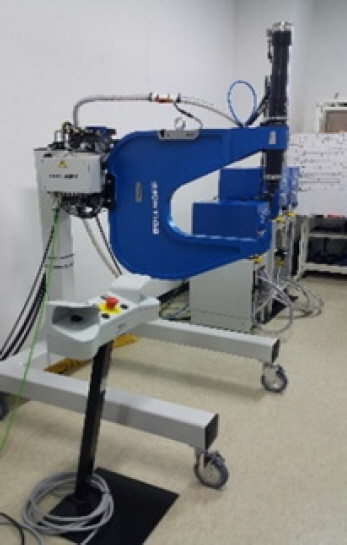
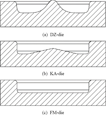
Fig. 4ņŚÉ ļ│┤ņØĖ Bollhoff ńżŠņØś Rivset GEN 2ļź╝ ņé¼ņÜ®ĒĢśņŚ¼ ņŗ£ĒŚśĒÄĖņØä ņĀ£ņ×æĒĢśņśĆņ£╝ļ®░, ņ£ĀņĢĢņןņ╣śļź╝ ņØ┤ņÜ®ĒĢśņŚ¼ punch forceļź╝ ņĄ£ļīĆ 78 kN Ļ╣īņ¦Ć ļ│ĆĒÖöĻ░Ć Ļ░ĆļŖźĒĢśņśĆļŗż. ņŗżĒŚśņŚÉņä£ ņé¼ņÜ®ļÉ£ C-type, HD2-type, HD3-type, P-type 4 ņóģļźśņØś rivet ļŗ©ļ®┤ņØä Fig. 6ņŚÉ ļéśĒāĆļé┤ņŚłļŗż. 4ņóģļźśņØś rivetņØś ņ×¼ņ¦łņØĆ ļ│┤ļĪĀĻ░Ģņ£╝ļĪ£ņŹ© AlmacņĮöĒīģņØ┤ ļÉśņ¢┤ņ׳ņ£╝ļ®░, 480 ┬▒ 30 HV ņØś Ļ▓ĮļÅäĻ░ÆņØä Ļ░Ćņ¦äļŗż. RivetņØĆ Fig. 6ņØś (A) ņĢäļל ļČĆļČäĻ│╝ rivetņØś ļüØļŗ©ņØĖ (C)ļČĆļČäņØś ĒśĢņāüņŚÉ ļö░ļØ╝ Ļ┤ĆĒåĄ Ļ░ĆļŖźĒĢ£ ņāüĒīÉņØś Ļ░ĢļÅäĻ░Ć ļŗ¼ļØ╝ņ¦äļŗż. C-type rivetņØĆ ļ╣äĻĄÉņĀü ļéĀņ╣┤ļĪ£ņÜ┤ ļüØļŗ©ņØś ĒśĢņāüņ£╝ļĪ£ ņāüĒīÉņØ┤ ņŚ░Ļ░ĢĻ│╝ ņĢīļŻ©ļ»ĖļŖäņØ╝ ļĢī ņé¼ņÜ®ļÉ£ļŗż. HD2 rivetņØĆ ņóĆ ļŹö ļæźĻĘ╝ ļüØļŗ©ņØś ĒśĢņāüņ£╝ļĪ£ņä£ Ļ│ĀĻ░ĢļÅäĻ░ĢĒīÉņŚÉ ņé¼ņÜ®ļÉ£ļŗż. HD3-typeņØĆ ļŁēĒłŁĒĢ£ ļüØļŗ©Ļ│╝ ņĢłņ¬ĮņØś ĒÖłņØ┤ ĻĄ┤Ļ│Īņ¦ä ĒśĢņāüņØ┤ļ®░ HD2- typeņŚÉ ļ╣äĒĢ┤ Ļ░ĢļÅäĻ░Ć ļåÆņØĆ Ļ░ĢĒīÉņŚÉ ņé¼ņÜ®ļÉ£ļŗż. ļ¦łņ¦Ćļ¦ēņ£╝ļĪ£ P-type rivetņØĆ ļüØļŗ©ņØś ĒśĢņāüņØ┤ 45┬░Ļ░üļÅäļĪ£ Ļ▓Įņé¼ņ¦ĆĻ▓ī Ļ╣ŹņØĖ ļ¬©ņä£ļ”¼ņØ┤ļ®░ ļæÉĻ╗ŹĻ▒░ļéś Ļ│ĀĻ░ĢļÅäĻ░ĢņŚÉ ņé¼ņÜ®ļÉ£ļŗż26). DieņØś ĒśĢņāüņØä ļ│ĆĒÖöĒĢśņŚ¼ ĒĢśĒīÉņŚÉņä£ rivetņØś ļŗżļ”¼Ļ░Ć ļ▓īņ¢┤ņ¦ĆļŖö interlockņØä ņĄ£ļīĆĒĢ£ ņ”ØĻ░Ćņŗ£ņ╝£ ņĀæĒĢ®ļČĆ Ļ░ĢļÅäļź╝ Ē¢źņāüņŗ£Ēé¼ ņłś ņ׳ļŗżļŖö ņØ┤ņĀäņØś ņŚ░ĻĄ¼ņŚÉ ļö░ļØ╝ die ĒśĢņāüņØä ļ│ĆĒÖöĒĢśļ®░ ņŗżĒŚśņØä ņŗżņŗ£ĒĢśĻ│Āņ×É ĒĢśņśĆļŗż17). DieļŖö ĒĢśļŗ©ļČĆĻ░Ć ĒÅēĒÅēĒĢ£ ĒśĢĒā£ņØś FM-type dieņÖĆ coneĒśĢĒā£ņØś KA-type die, Ļ░ĆņÜ┤ļŹ░Ļ░Ć ļåÆĻ▓ī ņå¤ņĢäņśżļź┤Ļ│Ā Ļ╣ŖĻ▓ī ĒīīņØĖ ĒśĢĒā£ņØś DZ-type die ņäĖ ņóģļźśļĪ£ ņ¦äĒ¢ēĒĢśņśĆņ£╝ļ®░ Fig. 7ņŚÉ Ļ░äļŗ©ĒĢ£ ļ¬©ņŗØļÅäļź╝ ļéśĒāĆļāłļŗż.

SPR ņĀæĒĢ®ņØś ņĀæĒĢ®ĒÆłņ¦ł ĒīÉļŗ©ņØä ņ£äĒĢ┤ Ļ┤æĒĢÖĒśäļ»ĖĻ▓Įņ£╝ļĪ£ ļŗ©ļ®┤ņØä Ļ┤Ćņ░░ĒĢśĻ│Ā Fig. 6Ļ│╝ Ļ░ÖņØ┤ head heightņÖĆ interlock, bottom thicknessņØś ņ╣śņłśļź╝ ņĖĪņĀĢĒĢśņśĆļŗż. ņØĖņןņĀäļŗ©ņŗ£ĒŚśņØĆ ļ¦īļŖźņ×¼ļŻīņŗ£ĒŚśĻĖ░ļź╝ ņé¼ņÜ®ĒĢśņśĆņ£╝ļ®░ 3 mm/minņØś ņåŹļÅäļĪ£ Ļ░ü ņĪ░Ļ▒┤ņØä 3ĒÜī ļ░śļ│Ą ņŗżņŗ£ĒĢśņśĆļŗż.
3. Ļ▓░Ļ│╝ ļ░Å Ļ│Āņ░░
3.1 Rivet ņóģļźśņŚÉ ļö░ļźĖ ņĀæĒĢ® ĒÆłņ¦ł ĒīÉļŗ©
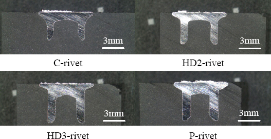
ņĢ×ņä£ ņäżļ¬ģĒĢ£ 4Ļ░Ćņ¦Ć ņóģļźśņØś rivetņŚÉ ļö░ļźĖ SPR ņĀæĒĢ®ļČĆ ĒÆłņ¦łĒīÉļŗ©ņØä ņ£äĒĢ┤ ņŗżĒŚśņØä ņ¦äĒ¢ēĒĢśņśĆļŗż. dieļŖö FM- typeņ£╝ļĪ£ Ļ│ĀņĀĢĒĢśņśĆņ£╝ļ®░, pre-clamping force 4 kN, punch forceļŖö 40 kNņ£╝ļĪ£ Ļ│ĀņĀĢĒĢśņśĆļŗż. ņĀæĒĢ®ņŗ£ĒÄĖņØś ļŗ©ļ®┤ļČĆļź╝ Fig. 8ņŚÉ ļéśĒāĆļé┤ņŚłņ£╝ļ®░, Fig. 6Ļ│╝ Ļ░ÖņØ┤ head height, interlock, bottom thicknessņØś Ēü¼ĻĖ░ļź╝ ņĖĪņĀĢĒĢśņśĆļŗż. head heightļŖö ņÖĖĻ┤Ć, ņĀæĒĢ®ļČĆņØś ĻĖ░ļ░Ćņä▒, rivetņŚÉ ņØśĒĢ£ ņāüĒīÉņØś ņåÉņāü ļō▒ņØä ļ░®ņ¦ĆĒĢśĻĖ░ ņ£äĒĢ┤ head heightĻ░ÆņØ┤ ņ×æņØäņłśļĪØ ļŹö ņóŗņØĆ ņĀæĒĢ®ļČĆļź╝ ĒśĢņä▒ĒĢ£ļŗż. Y. AbeņØś ņŚ░ĻĄ¼21) ņŚÉ ļö░ļź┤ļ®┤ interlock ĻĖĖņØ┤ņØś ņ”ØĻ░ĆņŚÉ ļö░ļØ╝ ņĀæĒĢ®Ļ░ĢļÅäĻ░Ć Ē¢źņāüļÉśļŖö Ļ▓āņ£╝ļĪ£ ļ│┤Ļ│ĀļÉśĻ│Ā ņ׳ļŗż. Interlock ĻĖĖņØ┤Ļ░Ć ņ”ØĻ░ĆĒĢśļ®┤ rivetņØä ņ×ĪĻ│Āņ׳ļŖö ĒĢśĒīÉņ£╝ļĪ£ļČĆĒä░ rivetņØä ļ╣╝ļé┤ĻĖ░ ņ£äĒĢ£ ņĀĆĒĢŁņØ┤ ņ”ØĻ░ĆĒĢśņŚ¼ ĒĢśĒīÉĻ│╝ ļŹö Ļ░ĢĒĢśĻ▓ī ņ▓┤Ļ▓░ļÉśĻĖ░ ļĢīļ¼ĖņŚÉ ņĀæĒĢ®ĒĢśņżæņØ┤ ņ”ØĻ░ĆĒĢ£ļŗż. Bottom thicknessļŖö ņĀæĒĢ®ĒĢśņżæņŚÉļŖö Ēü░ ņśüĒ¢źņØä ņŻ╝ņ¦Ć ņĢŖļŖö Ļ▓āņ£╝ļĪ£ ļ│┤Ļ│ĀļÉśĻ│Ā ņ׳ņ£╝ļéś ļČĆņŗØĻ│╝ ĒĢśĒīÉņØś ņ░óņ¢┤ņ¦ÉņØä ļ░®ņ¦ĆĒĢśĻĖ░ ņ£äĒĢ┤ ņØ╝ņĀĢ ļæÉĻ╗ś ņØ┤ņāüņØ┤ ņĀüĒĢ® ĒĢ£ Ļ▓āņ£╝ļĪ£ ļ│┤Ļ│ĀļÉśņŚłļŗż27).
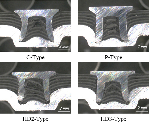
Fig. 8ņŚÉņä£ ļ│┤ņØ┤ļŖö Ļ▓āņ▓śļ¤╝ ļ¬©ļōĀ typeņŚÉņä£ rivet ļŗżļ”¼ņØś ņóīĻĄ┤Ļ│╝ Ļ░ÖņØĆ Ļ▓░ĒĢ©ņØĆ ĒÖĢņØĖļÉśņ¦Ć ņĢŖņĢśļŗż.
Fig. 9(a)ņŚÉņä£ head heightļŖö C-type rivetņØ┤ 0.38 mmļĪ£ Ļ░Ćņן ļé«ņĢśņ£╝ļ®░, HD2-typeņØĆ 0.57 mm, HD3-typeņØĆ 0.45 mm, P-type rivetņØ┤ 0.70 mmļĪ£ Ļ░Ćņן ļåÆņĢśļŗż. ņØ┤ļŖö rivetĻ│╝ ĒĢśĒīÉ ņé¼ņØ┤ņŚÉ ņ▒äņøīņ¦ä CFRPĻ░Ć ņĢĢņČĢ ļÉĀ ņłś ņŚåĻĖ░ ļĢīļ¼ĖņŚÉ rivet ņĢäļל ļČĆļČäņØ┤ ņāüļīĆņĀüņ£╝ļĪ£ Ļ│ĄĻ░äņØ┤ ļäōņØĆ C-type rivetņØ┤ Ļ░Ćņן ļé«ņØĆ head heightļź╝ ļéśĒāĆļāłļŗż.
InterlockņØĆ C-type rivetņØ┤ 0.35 mmļĪ£ ļŗżļźĖ typeņØś rivetņŚÉ ļ╣äĒĢ┤ ļŹö Ēü░Ļ░ÆņØä ļ│┤ņśĆļŗż. HD2-typeņØĆ 0 mm, HD3-typeņØĆ 0.02 mm, P-typeņØĆ 0.12 mmņØś ĻĖĖņØ┤ļĪ£ ņĖĪņĀĢļÉśņŚłļŗż. ņØ┤ļŖö HD2, P, HD3 typeņØś rivetņØś Ļ▓ĮņÜ░ Ļ░ĢļÅäĻ░Ć ļåÆĻ│Ā ņŚ░ņä▒ņØ┤ ļČĆņĪ▒ĒĢ£ Ļ│ĀĻ░ĢļÅäĻ░ĢņØ┤ ņāüĒīÉņŚÉ ņ£äņ╣śĒĢĀ ļĢī ņé¼ņÜ®ĒĢśĻĖ░ ļĢīļ¼ĖņØ┤ļŗż. Ļ│ĀĻ░ĢļÅäĻ░ĢņØä Ļ┤ĆĒåĄĒĢśĻĖ░ ņ£äĒĢ┤ Fig. 6ņØś (C)ļČĆļČäņØä ļŁēļææĒĢ£ ĒśĢņāüņ£╝ļĪ£ ļ│ĆĒÖöĒĢśĻ│Ā (A)ņĢłņ¬ĮņØś ĻĄ┤Ļ│ĪņØä ņŻ╝ņŚłĻĖ░ ļĢīļ¼ĖņŚÉ CFRPņÖĆ ņĢīļŻ©ļ»ĖļŖäņØś ņĀæĒĢ®ņŚÉņä£ļŖö ņāüļīĆņĀüņ£╝ļĪ£ interlockņØ┤ ņ¦¦ņĢäņ¦ĆĻ▓ī ļÉśņŚłļŗż.
Fig.┬Ā9
Graph of measurement factor and rivet types (a) head height, (b) interlock, (c) bottom thickness
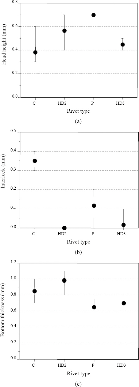
Bottom thicknessļŖö C-type rivetņØ┤ 0.85 mm, HD2-typeņØ┤ 0.98 mm, HD3-typeņØĆ 0.70 mm, P-typeņØĆ 0.65 mmļĪ£ ļäż ņóģļźśņØś rivetņØ┤ Ēü░ ņ░©ņØ┤ļź╝ ļ│┤ņØ┤ņ¦Ć ņĢŖņĢśļŗż. ļö░ļØ╝ņä£ CFRP ņāüĒīÉ Al5083 ĒĢśĒīÉņØś SPR Ļ▓╣ņ╣śĻĖ░ ņĀæĒĢ®ņŚÉņä£ interlockņØ┤ Ļ░Ćņן ĻĖĖĻ│Ā head heightĻ░Ć Ļ░Ćņן ļé«ņ£╝ļ®░ bottom thicknessĻ░Ć ņČ®ļČäĒĢ£ C-type rivetņØ┤ ļ│Ė ĒÅēĻ░ĆņŚÉ ņé¼ņÜ®ļÉ£ 4Ļ░Ćņ¦Ć SPR rivet ņżæ Ļ░Ćņן ņĀüĒĢ®ĒĢ£ Ļ▓āņ£╝ļĪ£ ĒīÉļŗ©ļÉ£ļŗż.
3.2 Die ĒśĢņāüņŚÉ ļö░ļźĖ ņĀæĒĢ® ĒÆłņ¦ł ĒīÉļŗ©
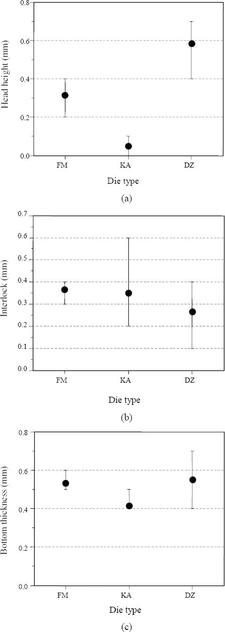
DieņØś ĒśĢņāüņŚÉ ļīĆĒĢ£ ņĀæĒĢ® ĒÆłņ¦ł ĒīÉļŗ©ņØä ņ£äĒĢ┤ Ļ░ü ĒśĢņāüņŚÉ ļö░ļźĖ SPR ņĀæĒĢ®ņŗżĒŚśņØä ņ¦äĒ¢ēĒĢśņśĆļŗż. ņĢ×ņä£ ņäĀņĀĢĒĢ£ C- type rivetĻ│╝ pre-clamping force 4 kN, punch forceļź╝ 39 kNņ£╝ļĪ£ Ļ│ĀņĀĢĒĢśņśĆļŗż. die ĒśĢņāüļ│ä ņŗżĒŚśņØä ņŗżņŗ£ĒĢ£ ņØ┤ņ£ĀļŖö interlockņØä ņĄ£ļīĆĒĢ£ ņ”ØĻ░Ćņŗ£ņ╝£ ņĀæĒĢ®ļČĆ Ļ░ĢļÅäļź╝ Ē¢źņāüņŗ£Ēé¼ Ļ▓āņ£╝ļĪ£ ĒīÉļŗ©ļÉśĻĖ░ ļĢīļ¼ĖņØ┤ļŗż17). ļö░ļØ╝ņä£ Fig. 7Ļ│╝ Ļ░ÖņØ┤ 3Ļ░Ćņ¦ĆņØś dieļź╝ ĒÅēĻ░ĆĒĢśņśĆļŗż. Fig. 11ņØś ĒÅēĻ░Ć Ļ▓░Ļ│╝ļź╝ ņóģĒĢ®ņĀüņ£╝ļĪ£ ĒīÉļŗ©ĒĢ£ Ļ▓░Ļ│╝, interlockņØś ĒÄĖņ░©Ļ░Ć ņ×æĻ│Ā ĒÅēĻĘĀĻ░ÆņØ┤ Ļ░Ćņן ļåÆņ£╝ļ®░ head heightĻ░Ć ļé«ņØĆ FM- typeņØś dieĻ░Ć ņāüĒīÉ CFRP ĒĢśĒīÉ Al5083ņØś SPR ņĀæĒĢ®ņŚÉņä£ļŖö Ļ░Ćņן ņĀüĒĢ®ĒĢśņśĆļŗż.
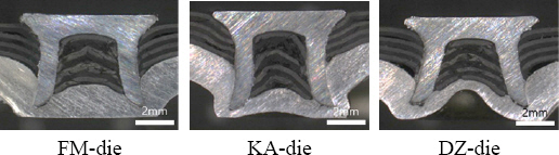
Fig.┬Ā11
Graph of measurement factor and die types (a) head height, (b) interlock, (c) bottom thickness
C-type rivetņŚÉ ļīĆĒĢ┤ ņäĖ ņóģļźśņØś dieļź╝ ņØ┤ņÜ®ĒĢśņŚ¼ ņĀæĒĢ®ĒĢ£ ņŗ£ĒÄĖņØś ļŗ©ļ®┤ņØä Fig. 10ņŚÉ ļéśĒāĆļé┤ņŚłļŗż. ļŗ©ļ®┤ņØä Ļ┤Ćņ░░ĒĢ£ Ļ▓░Ļ│╝ KAņÖĆ DZ typeņØś dieņØś Ļ▓ĮņÜ░ rivet ņżæņŗ¼ņäĀņ£╝ļĪ£ļČĆĒä░ ņóīņÜ░ ļīĆņ╣ŁņØ┤ ņĢäļŗłĻ▒░ļéś rivetņØś ņóīĻĄ┤ņØ┤ ņØ╝ņ¢┤ļéśļŖö Ļ▓ĮņÜ░ļōżņØ┤ Ļ┤Ćņ░░ļÉśņŚłļŗż. ņØ┤ļŖö DZ-typeņØś dieņØś Ļ▓ĮņÜ░ ņżæņŗ¼ļČĆĻ░Ć ļåÆĻ▓ī ņå¤Ļ│Ā Ļ░Ćņןņ×Éļ”¼Ļ░Ć Ļ╣Ŗņ¢┤, ĒĢśĒīÉņØĖ ņĢīļŻ©ļ»ĖļŖäņØś ņŚ░ņä▒ņØ┤ ļåÆņĢä ņä▒ĒśĢņØ┤ ņØ╝ņĀĢĒĢśņ¦Ć ņĢŖņØĆ Ļ▓āņ£╝ļĪ£ ĒīÉļŗ©ļÉ£ļŗż. ņ£äņÖĆ Ļ░ÖņØĆ ņØ┤ņ£ĀļĪ£ KA-typeĻ│╝ DZ-typeņØś dieņŚÉņä£ ņĖĪņĀĢĻ░ÆņØ┤ ņØ╝ņĀĢĒĢśņ¦Ć ņĢŖĻ│Ā Ēü░ ĒÄĖņ░©Ļ░Ć ļ░£ņāØĒĢśņŚ¼ ļ░śļ│Ąņ×¼Ēśäņä▒ņØ┤ ļČĆņĪ▒ĒĢśņśĆļŗż.
Fig. 11ņØś Ļ▓░Ļ│╝ņŚÉņä£ head heightļŖö KA-type dieņØś Ļ▓ĮņÜ░ 0.05 mmļĪ£ Ļ░Ćņן ņ×æņØĆ ļÅīņČ£ ĻĖĖņØ┤ļź╝ ļ│┤ņśĆļŗż. FM-type dieņØś Ļ▓ĮņÜ░ 0.32 mmņØś head height ĒÅēĻĘĀĻ░ÆņØä ļ│┤ņśĆņ£╝ļ®░, DZ-type dieņØś head height ĒÅēĻĘĀĻ░ÆņØĆ 0.58 mmļĪ£ Ļ░Ćņן ļåÆņĢśļŗż. ĻĘĖļ¤¼ļéś rivetņØ┤ ļ▓īņ¢┤ņ¦ĆļŖö interlockņØĆ FM-typeņØś dieĻ░Ć 0.37 mmļĪ£ Ļ░Ćņן ļåÆņĢśļŗż. KA-typeĻ│╝ DZ-type dieļŖö Ļ░üĻ░ü 0.35 mm, 0.26 mmņØś interlock ĒÅēĻĘĀĻ░ÆņØä ļ│┤ņśĆļŗż. Bottom thick- nessļŖö rivet ņóģļźśļ│ä ņŗżĒŚś Ļ▓░Ļ│╝ņÖĆ ļ¦łņ░¼Ļ░Ćņ¦ĆļĪ£ FM-type, KA-type, DZ-typeņØ┤ Ļ░üĻ░ü 0.53 mm, 0.42 mm, 0.55 mmļĪ£ 3Ļ░Ćņ¦ĆņØś die typeņŚÉ ļö░ļźĖ Ļ░ÆņØ┤ Ēü░ ņ░©ņØ┤ļź╝ ļ│┤ņØ┤ņ¦Ć ņĢŖņĢśļŗż. ļö░ļØ╝ņä£ ĒÄĖņ░©Ļ░Ć ņ×æĻ│Ā interlockĻ░ÆņØ┤ Ļ░Ćņן ļåÆņØĆ FM-type dieĻ░Ć ņĀüĒĢ®ĒĢ£ Ļ▓āņ£╝ļĪ£ ĒīÉļŗ©ĒĢśņśĆļŗż.
3.3 Punch forceņØś ļ│ĆĒÖöņŚÉ ļö░ļźĖ ņĀæĒĢ® ĒÆłņ¦ł ĒīÉļŗ©
SPR ņĀæĒĢ®ņØś Ļ│ĄņĀĢļ│ĆņłśņØĖ punch forceņŚÉ ļö░ļźĖ ņĀæĒĢ® ĒÆłņ¦łņØä ĒÅēĻ░ĆĒĢśĻĖ░ ņ£äĒĢ£ ņŗżĒŚśņØä ņŗżņŗ£ĒĢśņśĆļŗż.
ņĢ×ņäĀ ņŗżĒŚśņŚÉņä£ ņäĀņĀĢĒĢ£ C-type rivetĻ│╝ FM-type dieļź╝ ņé¼ņÜ®ĒĢśĻ│Ā pre-clamping forceļź╝ 4 kNņ£╝ļĪ£ Ļ│ĀņĀĢĒĢ£ ļÆż punch forceļź╝ ļ│ĆĒÖöņŗ£Ēéżļ®░ ņŗżĒŚśĒĢ£ ņĀæĒĢ®ļČĆņØś ļŗ©ļ®┤ņØä Fig. 12ņŚÉ ļéśĒāĆļé┤ņŚłļŗż. Punch ForceļŖö 29 kN ļČĆĒä░ 69 kNĻ╣īņ¦Ć 5 kN ļŗ©ņ£äļĪ£ ņ”ØĻ░Ćņŗ£ņ╝░ļŗż.

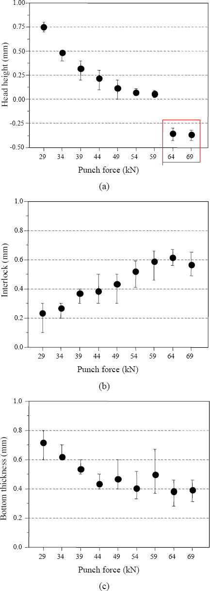
Fig. 13ņØś SPR ļŗ©ļ®┤ ĒÆłņ¦ł ņĖĪņĀĢ Ļ▓░Ļ│╝ņŚÉņä£ punch forceĻ░Ć ņ”ØĻ░ĆĒĢ©ņŚÉ ļö░ļØ╝ SPR rivetņØś head heightļŖö punch force 29 kNņØ╝ ļĢī 0.75 mmņØś Ļ░ÆņØä ļéśĒāĆļāłņ£╝ļ®░ punch forceĻ░Ć ņ”ØĻ░ĆĒĢ©ņŚÉ ļö░ļØ╝ņä£ head heightļŖö Ļ░ÉņåīĒĢśņŚ¼ punch force 69 kNņŚÉņä£ -0.4 mmĻ╣īņ¦Ć Ļ░ÉņåīĒĢśņśĆļŗż. ļ░śļ®┤ interlockņØĆ punch forceĻ░Ć ņ”ØĻ░ĆĒĢ©ņŚÉ ļö░ļØ╝ņä£ 0.23 mmņŚÉņä£ 0.61 mmĻ╣īņ¦Ć ņ”ØĻ░ĆĒĢśņśĆļŗż. Bottom thicknessļŖö punch force 29 kNņØ╝ ļĢī 0.72 mmļĪ£ ņĄ£ļīōĻ░ÆņØä ļéśĒāĆļāłņ£╝ļ®░ 64 kNņŚÉņä£ 0.38 mmņ£╝ļĪ£ ņĄ£ņå¤Ļ░ÆņØä ļéśĒāĆļāłļŗż. C-type rivetĻ│╝ FM-type dieļĪ£ ļÅÖņØ╝ĒĢ£ ņĪ░Ļ▒┤ņŚÉņä£ punch forceĻ░Ć ņ”ØĻ░ĆĒĢśļ®┤ rivetņØä ļŹöņÜ▒ Ļ░ĢĒĢśĻ▓ī ļłäļź┤ĻĖ░ ļĢīļ¼ĖņŚÉ head heightĻ░Ć Ļ░ÉņåīĒĢśņśĆņ£╝ļ®░, ņØ┤ļĪ£ ņØĖĒĢ┤ rivetņØś ļŗżļ”¼ļŖö ĒĢśĒīÉņØś ņĢīļŻ©ļ»ĖļŖäņŚÉņä£ ļŹö ļ¦ÄņØĆ interlockņØä ĒśĢņä▒ĒĢśņśĆļŗż. ļö░ļØ╝ņä£ head heightĻ░Ć ņāüĒīÉļ│┤ļŗż ļŹö Ļ╣ŖņØ┤ ņéĮņ×ģļÉśņ¢┤ ņāüĒīÉņØĖ CFRPņØś ņåÉņāüņØä ņØ╝ņ£╝Ēé© punch force 64 kNņØ┤ņāüņØä ņĀ£ņÖĖĒĢśĻ│Ā, punch force 59 kN ņØ╝ ļĢī Ļ░Ćņן head heightĻ░Ć ļé«Ļ│Ā interlockņØ┤ Ēü¼ļ®░ bottom thicknessĻ░Ć ņČ®ļČäĒĢ£ ņĪ░Ļ▒┤ņ£╝ļĪ£ ļéśĒāĆļé¼ļŗż.
3.4 Punch force ļ│ĆĒÖöņŚÉ ļö░ļźĖ ņĀæĒĢ®ĒĢśņżæ
Ļ│ĄņĀĢļ│ĆņłśņØś ļ│ĆĒÖöņŚÉ ļö░ļźĖ ņĄ£ņĀüņØś ņĀæĒĢ®ĒĢśņżæņØä ļÅäņČ£ĒĢśĻĖ░ ņ£äĒĢ┤ ņØĖņןņĀäļŗ©ņŗ£ĒŚśņØä ņŗżņŗ£ ĒĢśņśĆļŗż. Fig. 14(a)ņØś ņØĖņןĒĢśņżæ ĻĘĖļלĒöäņŚÉņä£ ļ│┤ņØ┤ļŖö Ļ▓āņ▓śļ¤╝ CFRPĻ░Ć ņ▓śņØī Ēīīļŗ©ņØ┤ ņØ╝ņ¢┤ļéśĻĖ░ ņŗ£ņ×æĒĢĀ ļĢīņØś Ļ░ÆņØä CFRPņØś first fracture loadļĪ£ ņĀĢņØśĒĢśņśĆņ£╝ļ®░, ņĄ£ļīĆ ĒĢśņżæ Ļ░ÆņØä maximum fracture loadļĪ£ ņĀĢņØśĒĢśņśĆļŗż. Fig. 14(c)ņØś ņØĖņןņĀäļŗ©ņŗ£ĒŚś Ļ▓░Ļ│╝ņŚÉņä£ CFRPņØś first fracture loadļŖö punch force 29 kNņŚÉņä£ ņĄ£ņå¤Ļ░Æ 2.4 kNņØ┤ņŚłņ£╝ļ®░, punch forceĻ░Ć ņ”ØĻ░ĆĒĢ©ņŚÉ ļö░ļØ╝ Ļ░ÖņØ┤ ņ”ØĻ░ĆĒĢśņŚ¼ punch force 54 kNņŚÉņä£ ņĄ£ļīōĻ░Æ ņĢĮ 4.4 kNņŚÉ ļÅäļŗ¼ĒĢśņśĆļŗż.
Fig.┬Ā14
Tensile shear test of SPR joints (a) location of first fracture load and maximum fracture load, (b) load-displacement curve of punch force 59 kN, (c) tensile shear load of punch force

Maximum fracture loadļŖö punch force 54 kN ņŚÉņä£ ņĢĮ 4.6 kNĻ░ÆņØä ņ¢╗ņŚłļŗż. ņĄ£ņå¤Ļ░ÆņØĆ punch force 29 kNņŚÉņä£ 3.3 kN ņØś ĒĢśņżæņØä ļ│┤ņśĆļŗż. maximum fracture loadļŖö punch force 29 kNņØś Ļ░Ćņן ļé«ņØĆ Ļ░ÆņØä ņĀ£ņÖĖĒĢśĻ│Ā punch forceņØś ļ│ĆĒÖöņŚÉ ļö░ļØ╝ ņØ╝ņĀĢĒĢ£ Ļ▓ĮĒ¢ź ņŚåņØ┤ ņĢĮ 4 kNņŚÉņä£ 4.5 kNņé¼ņØ┤ņŚÉ ļČäĒżĒĢśņśĆļŗż.
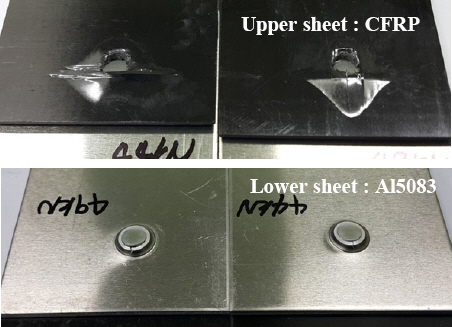
Fig. 15ņØś Ēīīļŗ©ĒśĢņāüņŚÉņä£ ļ│┤ņØ┤ļŖö Ļ▓āņ▓śļ¤╝ ļ│Ė ņŗżĒŚśņĪ░Ļ▒┤ņŚÉņä£ļŖö rivetņØ┤ CFRPņÖĆ Al5083ņØś ņĀæĒĢ®ļČĆņŚÉ Ļ░ĢĒĢśĻ▓ī ņ▓┤Ļ▓░ļÉśņŚłĻĖ░ ļĢīļ¼ĖņŚÉ rivetņØ┤ ļĮæĒśĆ ļéśņśżļŖö pull-outņØś Ēīīļŗ©ļ¬©ļō£Ļ░Ć ļ░£ņāØĒĢśņ¦Ć ņĢŖņĢśņ£╝ļ®░, ņāüĒīÉ CFRP ļ¬©ņ×¼ņØś ļ▓Āņ¢┤ļ¦ü Ēīīļŗ©ņØ┤ ļ░£ņāØĒĢśņśĆļŗż. CFRPļŖö ņØĖņןĒĢśņżæ ņŗżĒŚśņØ┤ ņ¦äĒ¢ēļÉ©ņŚÉ ļö░ļØ╝ fiberĻ░Ć ņŚ░ņćäņĀüņ£╝ļĪ£ Ēīīļŗ©ļÉśņ¢┤ Fig. 14(a)ņØś ĒĢśņżæ-ļ│Ćņ£ä ĻĘĖļלĒöäņŚÉņä£ ļ│┤ņØ┤ļŖö Ļ▓āņ▓śļ¤╝ ļ¬ć ļ▓łņØś peak Ļ░ÆņØä ļéśĒāĆļéĖļŗż28). ņØ┤Ēøä ļ▓Āņ¢┤ļ¦ü Ēīīļŗ©ņØ┤ Ļ│äņåŹļÉśņ¢┤ CFRPĻ░Ć rivetņØä ņ×ĪņĢäļŗ╣ĻĖ░Ļ▓ī ļÉśĻ│Ā, rivetņØ┤ ĒÜīņĀäĒĢśļ®░ ĒĢśĒīÉ ņĢīļŻ©ļ»ĖļŖäņØś ĒīīņåÉņØ┤ ņØ╝ņ¢┤ļéśļ®░ ņĄ£ļīĆĒĢśņżæņØ┤ ļ░£ņāØĒĢ£ļŗż29,30). CFRPņØś Ēīīļŗ©ņØĆ punch forceĻ░Ć ļé«ņØä ļĢīņŚÉļŖö Fig. 14(a)ņØś ĒĢśņżæ-ļ│Ćņ£ä ĻĘĖļלĒöäņ▓śļ¤╝ fiberĻ░Ć ņ▓śņØī Ēīīļŗ©ņØ┤ ņŗ£ņ×æ ļÉ£ ņØ┤Ēøä ņŚ░ņåŹņĀüņØĖ fiber Ēīīļŗ©ņ£╝ļĪ£ ņØĖĒĢ┤ maximum fracture loadņŚÉ ļÅäļŗ¼ĒĢśĻ▓ī ļÉśņŚłļŗż. ĻĘĖļ¤¼ļéś punch forceĻ░Ć ņ”ØĻ░ĆĒĢ©ņŚÉ ļö░ļØ╝ Fig. 14(b)ņØś ĒĢśņżæ-ļ│Ćņ£ä ĻĘĖļלĒöäņÖĆ Ļ░ÖņØ┤ CFRPņØś fiberĻ░Ć ņ▓śņØī Ēīīļŗ©ņØä ņŗ£ņ×æĒĢśļŖö ĒĢśņżæņØ┤ ņĀÉņ░© ņ”ØĻ░ĆĒĢśņŚ¼ maximum fracture loadņÖĆ Ļ░ÖĻ▒░ļéś ļ╣äņŖĘĒĢ£ Ļ░ÆĻ╣īņ¦Ć ļÅäļŗ¼ĒĢ£ ļÆż ņŚ░ņåŹņĀüņØĖ ļ▓Āņ¢┤ļ¦ü Ēīīļŗ©ņØ┤ ņ¦äĒ¢ēļÉśļ®░ ņĀæĒĢ®ļČĆĻ░Ć ĒīīņåÉļÉśņŚłļŗż. ņØ┤ļĪ£ ņØĖĒĢ┤ Fig. 14(c)ĻĘĖļלĒöäņŚÉņä£ punch forceĻ░Ć ņ”ØĻ░ĆĒĢ©ņŚÉ ļö░ļØ╝ CFRPņØś first fracture loadņÖĆ maximum fracture loadĻ░ÆņØś ņ░©ņØ┤Ļ░Ć Ļ░ÉņåīĒĢśņśĆļŗż. ņØ┤ļŖö punch forceĻ░Ć ņ”ØĻ░ĆĒĢśļ®┤ SPRņØś rivet headĻ░Ć CFRPļź╝ ļłäļź┤ļŖö ĒלņØ┤ ņ”ØĻ░ĆĒĢśņŚ¼ CFRPņØś first frac ļ│Ė ļģ╝ļ¼ĖņŚÉņä£ļŖö CFRPņØś first fracture loadņÖĆ maximum fracture loadļź╝ ļ¬©ļæÉ ņĖĪņĀĢĒĢśņŚ¼ ĻĖ░ņ×¼ĒĢśņśĆļŗż.
3.5 ņĖĪņĀĢņØĖņ×É Ļ░ÆĻ│╝ Ēīīļŗ©ņŗ£ņĀÉņŚÉ ļö░ļźĖ ĒĢśņżæņØś Ļ┤ĆĻ│ä
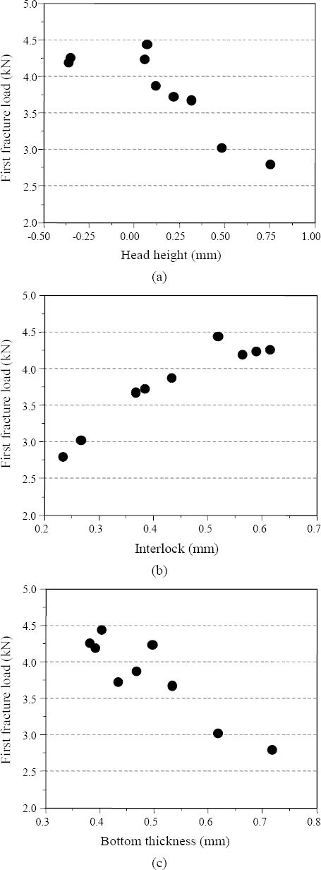
Fig. 16ņ▓śļ¤╝ SPR ņĀæĒĢ® ņŗ£ĒÄĖņØś maximum fracture loadņØś Ļ▓ĮņÜ░ 4~4.6 kNņØś ļ▓öņ£äļź╝ ļ│┤ņØ┤ļ®░ head height, interlock, bottom thicknessņØś ĻĖĖņØ┤ņŚÉ ļö░ļźĖ Ēü░ ņ░©ņØ┤ļź╝ ļ│╝ ņłś ņŚåņŚłļŗż. ņØ┤ļŖö ņ£äņØś ņŗżĒŚśņŚÉņä£ CFRPņÖĆ ņĢīļŻ©ļ»ĖļŖäņØś SPR ņĀæĒĢ®ļČĆņŚÉņä£ ņĖĪņĀĢĒĢ£ ņØĖņ×ÉļōżņØś ņ▓┤Ļ▓░ļĀźņØ┤ ņČ®ļČäĒĢśņŚ¼ CFRPņØś ļ¬©ņ×¼Ļ░Ć Ēīīļŗ©ļÉśĻĖ░ ļĢīļ¼ĖņØ┤ļŗż. Fig. 17ņ▓śļ¤╝ CFRPņØś first fracture loadņØś Ļ▓ĮņÜ░ head height ņÖĆ bottom thicknessĻ░Ć ņ”ØĻ░ĆĒĢ©ņŚÉ ļö░ļØ╝ ĒĢśņżæĻ░ÆņØ┤ Ļ░ÉņåīĒĢśņśĆņ£╝ļ®░, interlockņØ┤ ņ”ØĻ░ĆĒĢ©ņŚÉ ļö░ļØ╝ņä£ ĒĢśņżæĻ░ÆņØ┤ ņ”ØĻ░ĆĒĢśļŖö Ļ▓āņØä ļ│╝ ņłś ņ׳ņŚłļŗż. ļö░ļØ╝ņä£ ļ│Ė ņĀĆņ×ÉļŖö CFRPņÖĆ Al5083ņØś SPR ņĀæĒĢ®ņŗ£ņŚÉ CFRPņØś first fracture loadļź╝ maximum fracture loadĻ╣īņ¦Ć ņ”ØĻ░Ćņŗ£ņ╝£ ņāüĒīÉ ļ¬©ņ×¼ Ēīīļŗ© ĒĢśņżæņØä Ē¢źņāüņŗ£ĒéżļŖö Ļ▓āņØ┤ ņżæņÜöĒĢśļŗżĻ│Ā ĒīÉļŗ©ĒĢśņśĆļŗż.

4. Ļ▓░ ļĪĀ
CFRPņÖĆ Al5083-OņØś ņØ┤ņóģņ×¼ļŻīĻ░äņØś SPR ņĀæĒĢ® ļ░®ļ▓ĢņØä ņŚ░ĻĄ¼ĒĢśĻĖ░ ņ£äĒĢśņŚ¼, rivet typeĻ│╝ die type, punch forceļź╝ ļ│ĆĒÖöņŗ£Ēéżļ®░ ņŗżĒŚśņØä ņ¦äĒ¢ēĒĢśņśĆļŗż. ļśÉĒĢ£, punch forceņŚÉ ļö░ļźĖ ņØĖņן ņĀäļŗ©ņŗ£ĒŚśņØä ņ¦äĒ¢ēĒĢśņŚ¼ ņĖĪņĀĢ ņØĖņ×ÉļōżņØ┤ ņØĖņןĻ░ĢļÅäņŚÉ ņŻ╝ļŖö ņśüĒ¢źņØä ņĪ░ņé¼ĒĢśņśĆļŗż. ļö░ļØ╝ņä£ ņØ┤ ņŚ░ĻĄ¼ņŚÉņä£ ļŗżņØīĻ│╝ Ļ░ÖņØĆ Ļ▓░ļĪĀņØä ņ¢╗ņŚłļŗż.
1) ņāüĒīÉņØś 1.8 mm CFRPņÖĆ ĒĢśĒīÉ 2.0 mm Al5083 ņĪ░ĒĢ®ņŚÉņä£ ņĖĪņĀĢņØĖņ×ÉņØĖ head heightņÖĆ interlock ĻĖĖņØ┤, bottom thicknessļź╝ Ļ│ĀļĀżĒĢśņśĆņØä ļĢī head heightĻ░Ć ļé«Ļ│Ā interlockņØ┤ Ēü¼ļ®░ bottom thicknessĻ░Ć ņČ®ļČäĒĢ£ C-type rivetĻ│╝ FM-type dieĻ░Ć Ļ░Ćņן ņĀüĒĢ®ĒĢśņśĆļŗż.
2) Punch forceņØś ļ│ĆĒÖöņŚÉ ļö░ļźĖ ņØĖņןĻ░ĢļÅä ņŗ£ĒŚśņŚÉņä£ CFRPņØś first fracture loadņÖĆ maximum fracture loadļź╝ ņĀĢņØśĒĢśĻ│Ā punch force 54 kNņŚÉņä£ CFRPņØś first fracture loadĻ░Ć ņĄ£ļīĆ 4.4 kNĻ╣īņ¦Ć ļÅäļŗ¼ĒĢśņśĆļŗż.
3) SPR ņĀæĒĢ®ņŚÉņä£ ņĀæĒĢ®ņä▒ņØä ĒīÉļŗ©ĒĢśļŖö ņĖĪņĀĢņØĖņ×ÉņØĖ head height, interlock, bottom thicknessņÖĆ Ēīīļŗ© ņŗ£ņĀÉņŚÉ ļö░ļźĖ ĒĢśņżæņØĖ CFRPņØś first fracture load, maximum fracture loadņÖĆņØś Ļ┤ĆĻ│äļź╝ ĒÖĢņØĖĒĢśņśĆļŗż. ņ£äņØś ņĖĪņĀĢņØĖņ×ÉļōżņØĆ maximum fracture loadņŚÉļŖö Ēü░ ņśüĒ¢źņØä ņŻ╝ņ¦Ć ņĢŖņĢśņ£╝ļéś, CFRPņØś first fracture loadļŖö head heightņÖĆ bottom thicknessĻ░Ć Ļ░ÉņåīĒĢśĻ│Ā, interlockņØ┤ ņ”ØĻ░ĆĒĢĀņłśļĪØ Ēīīļŗ©ĒĢśņżæņØ┤ ņ”ØĻ░ĆĒĢśļŖö Ļ▓āņØä ĒÖĢņØĖĒĢśņśĆļŗż.
ļ│Ė ņŚ░ĻĄ¼ņŚÉņä£ļŖö CFRPņÖĆ Al ņĪ░ĒĢ®ņŚÉņä£ņØś SPR ņ▓┤Ļ▓░ ņŗ£ ņĀæĒĢ®ļČĆ ĒÆłņ¦ł ĒīÉļŗ© ĻĖ░ņżĆĻ│╝, ņĖĪņĀĢņØĖņ×ÉņÖĆ ņĀæĒĢ®ĒĢśņżæĻ│╝ņØś ņāüĻ┤ĆĻ┤ĆĻ│äļź╝ ņäżļ¬ģĒĢśĻ│Āņ×É ĒĢśņśĆļŗż.
 PDF Links
 PubReader
 ePub Link
 Full text via DOI
 Download Citation
 Print
Print


